
Steerable medical device having means for imparting curves in the device and in elongated implantable medical instruments

Active Publication Date: 2006-09-05
MEDTRONIC INC
View PDF22 Cites 42 Cited by
  • Summary
  • Abstract
  • Description
  • Claims
  • Application Information

AI Technical Summary

Benefits of technology

[0026]The invention is therefore directed to improvements in a steerable elongated medical devices, adapted to be advanced through a tortuous pathway to a desired location and having a small diameter body that is simple and inexpensive to manufacture, resists kinking, and that can be manipulated easily to control the deflection of and impart a wide degree of dynamic curvature in a distal segment of the device.
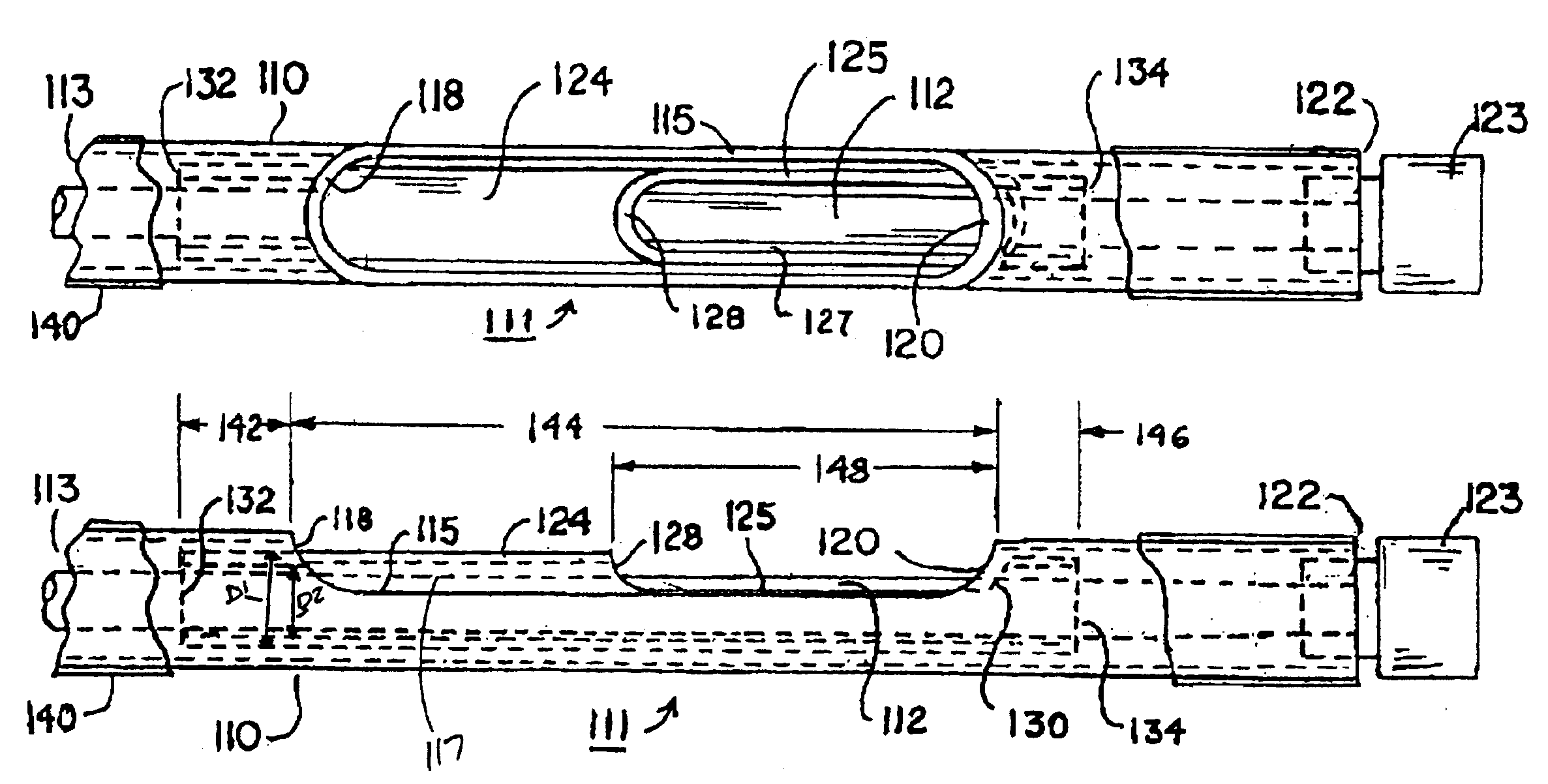
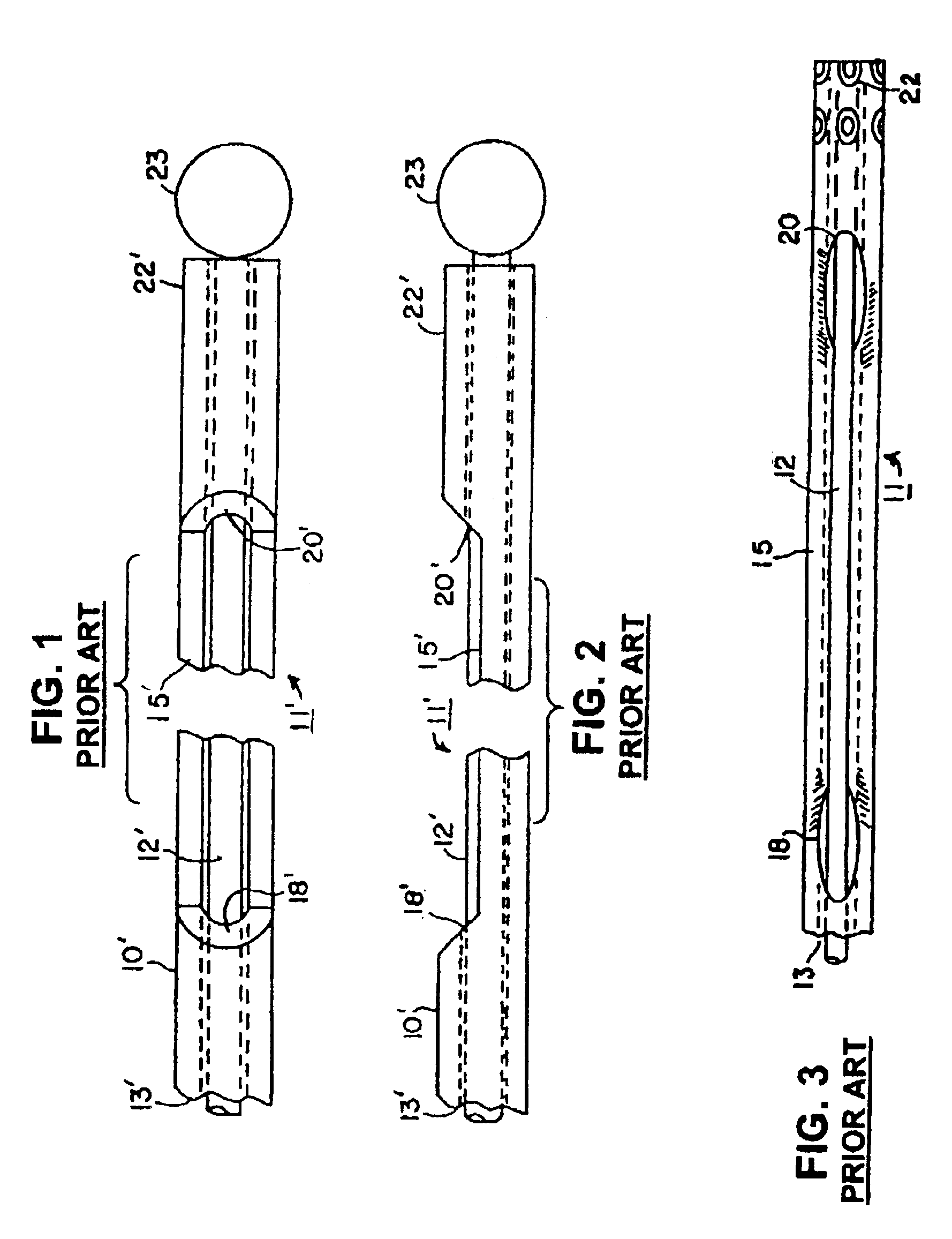
[0032]Advantageously, the inclusion of the reinforcement sleeve resists the buckling encountered in testing the prior art steerable stylet design illustrated in FIGS. 1 and 2. Moreover, fabrication is simplified compared with the fabrication of prior art steerable medical devices.
[0033]The above-described steerable medical devices of the present invention advantageously facilitate the direct implantation of elongated cardiac leads having stylet lumens or the introduction and steering of guide catheters to a site of implantation of such cardiac leads or other medical devices or therapeutic or diagnostic substances. The features of the present invention can advantageously be incorporated into steerable stylets that impart or enhance torqueability and impart steerability to guide catheter distal ends.

Problems solved by technology

The introduction and fixation of these cardiac leads is the most time consuming and difficult aspect of the implantation.
However, dislodgements can occur before the fixation is effected when a stylet is withdrawn proximally as the stylet may bind against the lead body lumen in the region of the bend.
During handing, such stylets can easily become bent or kinked, and thereafter cause great difficulty when an attempt is made to reinsert them through the narrow inner diameter of the lead body lumen, which may only be 0.019 inch in the case of a stylet of 0.018 inch diameter, thereby providing no more than 0.0005 inch clearance around the circumference.
The continual withdrawal and reintroduction of stylets is time consuming and offers the potential of damaging the lead in the process.
Moreover, it is undesirable to contaminate the lead body lumen with blood during this process because drying blood can form a strong adhesive bond between the stylet and the lumen wall, making stylet removal impossible and rendering the lead unusable.
When the stylet jams in the lead body lumen, kinking of the stylet within the lead can occur, which kinks, in turn, will create new jams or problems with the insertion and retraction of the stylet from the lead body lumen.
In some cases, the jamming is so severe that the cardiac lead must be removed from the heart for fear of insulation puncture, discarded, and a new lead implanted, thereby at least doubling the lead cost used in the procedure as well as operative time.
The overall result of such difficulties is that operative time is greatly increased, which results in increased time delay, associated cost, and prolonged X-ray exposure to the patient under continuous fluoroscopy as well as prolonged scattered X-ray exposure to the operating room staff due to procedural time delays.
In addition, the complexity of cardiac leads, the number of cardiac leads implanted in a common path, and the advancement of coronary sinus leads deep in a coronary vein have led to efforts to at least not increase and optimally to decrease the overall diameter of the cardiac lead body without sacrificing reliability and usability.
As a result, the small diameter lead bodies lack “pushability”, that is the ability to advance the lead distal end axially when the lead proximal end is pushed axially, particularly when the lead body extends through the tortuous transvenous pathway.
However, It can be difficult to indent thin wall stainless steel or shape memory alloy tubes to achieve the uniform indentation depicted in the '119 patent.
It can also be difficult to precisely form uniform diameter proximal and distal holes as depicted in the '119 patent.
Poor torque transmission and uneven bending characteristics can result particularly at the proximal end of the indented portion 11 that is weakened both by indentation and formation of the hole through the tube wall.

Method used


Image

  • Steerable medical device having means for imparting curves in the device and in elongated implantable medical instruments
  • Steerable medical device having means for imparting curves in the device and in elongated implantable medical instruments
  • Steerable medical device having means for imparting curves in the device and in elongated implantable medical instruments

Examples


Embodiment Construction

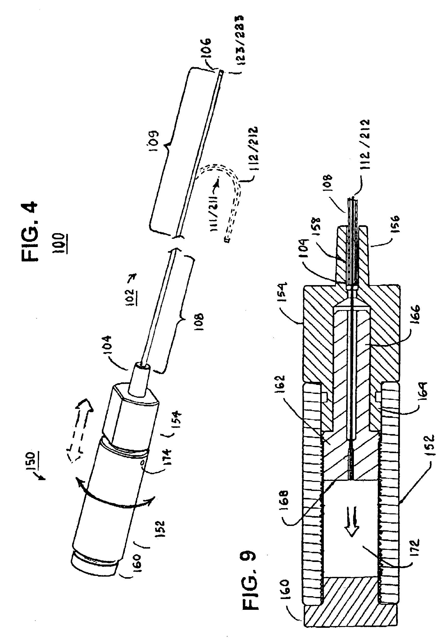
[0046]In the following detailed description, references are made to illustrative embodiments for carrying out the invention. It is understood that other embodiments may be utilized without departing from the scope of the invention. Although the present invention is described as preferably being applied to a steerable stylet, the aspects of the present invention are not intended to be limited to use in steerable stylets. Rather, it is understood that the present invention could be utilized in elongated medical devices other than steerable stylets, such as sheaths or catheters, for example. The preferred embodiments of the steerable stylets of the present invention can be employed within the lumens of endocardial cardiac leads, particularly endocardial pacing and / or cardioversion / defibrillation leads, but it will be understood that the steerable stylets of present invention can be utilized in any elongated medical instruments of the types described or mentioned herein and equivalents ...


PUM


Abstract

A steerable elongated medical device adapted to be advanced through a tortuous pathway to a desired location in a body includes an outer tube extending between an outer tube proximal segment and an outer tube distal segment, having an outer tube wall forming an outer tube lumen and an elongated outer tube slot through the outer tube wall to the outer tube lumen. The elongated outer tube slot has a first portion and a second portion and is formed between an outer tube slot proximal end and an outer tube slot distal end and extending axially along the outer tube distal segment through an outer tube slot length to define a cutaway portion of the outer tube. A reinforcing sleeve is positioned within the outer tube lumen and extends between a reinforcing sleeve proximal end and a reinforcing sleeve distal end, and the reinforcing sleeve forms a reinforcing sleeve slot portion aligned with and extending along the first portion of the outer tube slot and includes a reinforcing sleeve overlap portion extending over the second portion of the outer tube slot.

Description

FIELD OF THE INVENTION[0001]The present invention pertains to the permanent or temporary implantation of elongated medical instruments in the body or used to access a site in the body to facilitate introduction of a further medical device, and particularly to elongated steerable medical devices, such as a steerable stylets, for steering the distal end and imparting curves in distal segments of such medical instruments to facilitate implantation.BACKGROUND OF THE INVENTION[0002]A wide variety of elongated medical instruments are currently available that are adapted to be permanently or temporarily implanted in the mammalian body, usually the body of a human patient, or used to access a site in the body to facilitate introduction of a further implantable medical device or delivery of a therapeutic or diagnostic agent. Such elongated medical instruments have an instrument body extending between instrument body proximal and distal ends, and a distal segment of the instrument body is adv...

Claims


Application Information

Patent Timeline
IPC IPC(8): A61M25/00A61M25/01
CPCA61M25/0136A61M25/0147A61M25/0144A61M25/0138
Inventor GARDESKI, KENNETH C.
Owner MEDTRONIC INC
Learn More