AI technical title is built by PatSnap AI team. It summarizes the technical point description of the patent document.
a luminescence device and organic technology, applied in the field of organic luminescence devices, can solve the problems of insufficient luminescence efficiency, change in luminance, emission luminance and durability, and accompanied by durability
Inactive Publication Date: 2003-01-09
CANON KK
View PDF0 Cites 51 Cited by
Summary
Abstract
Description
Claims
Application Information
AI Technical Summary
This helps you quickly interpret patents by identifying the three key elements:
Problems solved by technology
Method used
Benefits of technology
Benefits of technology
[0011] A specific object of the present invention is to provide an organic luminescence device capable of effecting output of light with very high efficiency and luminance by using a specific fused polynuclear aromatic compound.
[0013] A further object of the present invention is to provide an organic luminescence device which can be prepared readily and relatively inexpensively.
Problems solved by technology
Further, the organic luminescence devices have been accompanied with problems in terms of durability such as a change in luminance with time due to continuous use for a long time, and a deterioration (e.g., an occurrence of dark spots due to leakage of current) by ambient gas containing oxygen or by humidity.
However, resultant emission luminances and durabilities and luminescence efficiencies have been still insufficient.
Method used
Image
Click on the blue label to locate the original text in one second.
Reading with bidirectional positioning of images and text.
Examples
examples 2-15
[0084] Organic luminescence devices were prepared and evaluated in the same manner as in Example 1 except that the fused polynuclear compound (Ex. Comp. No. 1) was changed to those (Ex. Comp. Nos. 4, 8, 10, 13, 16, 18, 20, 23, 24, 26, 28, 32, 34 and 35), respectively.
[0085] The results are shown in Table 1.
example 16
[0094] An organic luminescence device shown in FIG. 3 was prepared in the following manner.
[0095] In a similar manner as in Example 1, a transparent electroconductive support was prepared.
[0096] On the transparent electroconductive support, a 40 nm-thick hole transport layer 5 of a compound shown below was formed by vacuum deposition. 19
[0098] On the luminescence layer 3, a 40 nm-thick electrontransport layer 6 of a fused polynuclear compound (Ex. Comp. No. 2) was formed by vacuum deposition (1.0.times.10.sup.-4 Pa;0.2-0.3 nm / sec).
[0099] Then, on the electrontransport layer 6, a 150 nm-thick metalelectrode (cathode 4) of an aluminum-lithiumalloy (Li content: 1 atomic %) was formed by vacuum deposition (1.0.times.10.sup.-4 Pa;1.0-1.2 nm / sec).
[0100] To the thus-prepared organic luminescence device as shown in FIG. 3, a DC voltage of 8 volts was appl...
examples 17-30
[0102] Organic luminescence devices were prepared and evaluated in the same manner as in Example 16 except that the fused polynuclear compound (Ex. Comp. No. 2) was changed to those (Ex. Comp. Nos. 6, 9, 12, 15, 17, 19, 21, 22, 25, 27, 29, 30, 31 and 33), respectively.
[0103] The results are shown in Table 3.
PUM
Property
Measurement
Unit
thickness
aaaaa
aaaaa
thickness
aaaaa
aaaaa
luminance
aaaaa
aaaaa
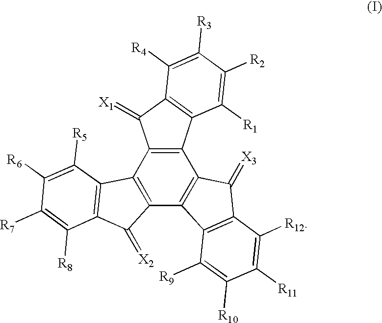
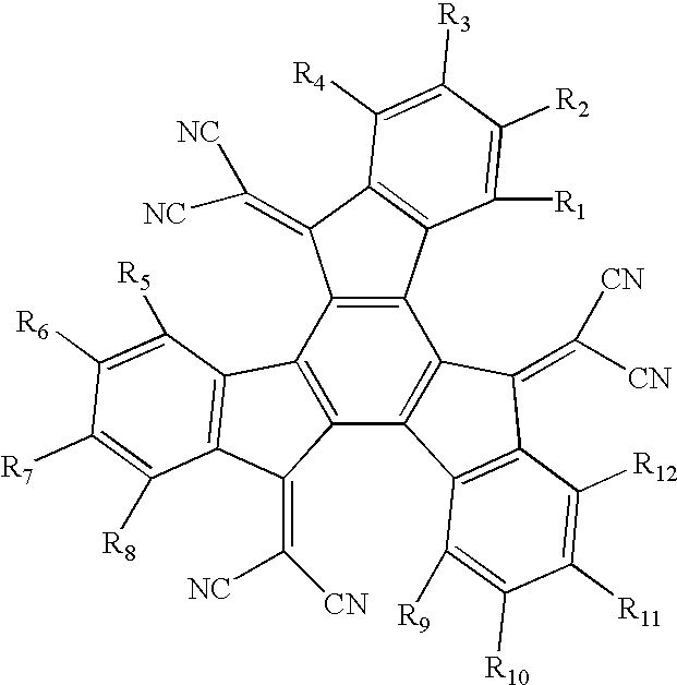
Abstract
An organic luminescence device is constituted by a pair of an anode and a cathode, and at least one organic layer disposed between the anode and the cathode. The above-mentioned at least one organic layer includes a layer of a fused polynuclear compound represented by the following formula (I): In the above formula (I), X1, X2 and X3 may preferably oxygen atom or C(CN)2. The device using the fused polynuclear compound of the formula (I) exhibits a high-luminance luminescence characteristic for a long period of time.
Description
FIELD OF THE INVENTION AND RELATED ART[0001] The present invention relates to an organic luminescence device using a specific fused polynuclear (or polycyclic) compound, particularly an organic luminescence device wherein an electric field is applied to a film of an organic compound comprising the fused polynuclear compound to cause luminescence.[0002] An organic luminescence device is a device such that a thin film containing a fluorescent organic compound is sandwiched between an anode and a cathode, and holes and electrons are injected from the anode and the cathode, respectively, into the fluorescent organic compound layer to generate excitons which emit light at the time of being returned to a ground state.[0003] For example, according to Eastman Kodak's study ("Appl. Phys. Lett.", 51,913 (1987)), when a voltage of ca. 10 volts is applied to a function separation-type organic luminescence device including two layers of an aluminum quinolinol complex (as electron transport and l...
Claims
Application Information
Patent Timeline
Application Date:The date an application was filed.
Publication Date:The date a patent or application was officially published.
First Publication Date:The earliest publication date of a patent with the same application number.
Issue Date:Publication date of the patent grant document.
PCT Entry Date:The Entry date of PCT National Phase.
Estimated Expiry Date:The statutory expiry date of a patent right according to the Patent Law, and it is the longest term of protection that the patent right can achieve without the termination of the patent right due to other reasons(Term extension factor has been taken into account ).
Invalid Date:Actual expiry date is based on effective date or publication date of legal transaction data of invalid patent.
Patent Type & AuthorityApplications(United States)

