Pinch valve

Inactive Publication Date: 2003-01-16
ASAHI YUKIZAI KOGYO CO LTD
View PDF2 Cites 47 Cited by
  • Summary
  • Abstract
  • Description
  • Claims
  • Application Information

AI Technical Summary

Benefits of technology

0005] The present invention has been conceived in view of the problems of the prior art as stated above, and the purpose of this invention is to provide a pinch valve the overall height of which is low in comparison with th

Problems solved by technology

Consequently, the above pinch valve cannot be used as a pinch valve in the pipeline of a semiconductor manufacturing apparatus.
Also, since, in the pinch valve

Method used


Image

  • Pinch valve
  • Pinch valve
  • Pinch valve

Examples


first embodiment

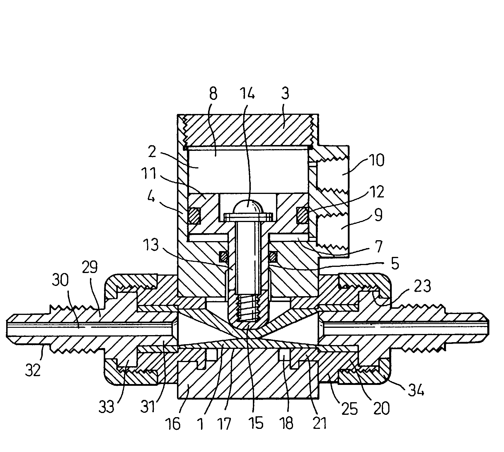
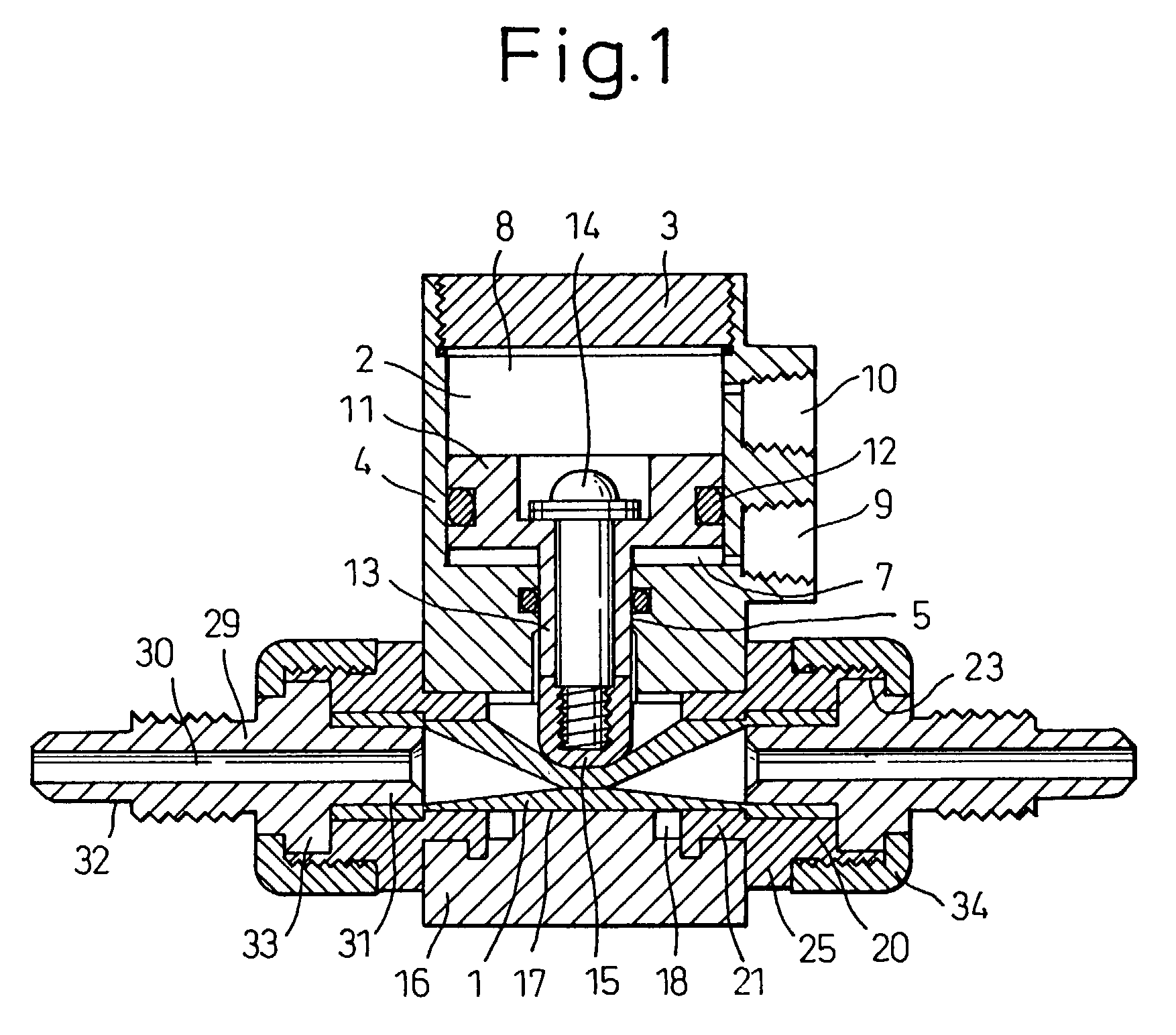
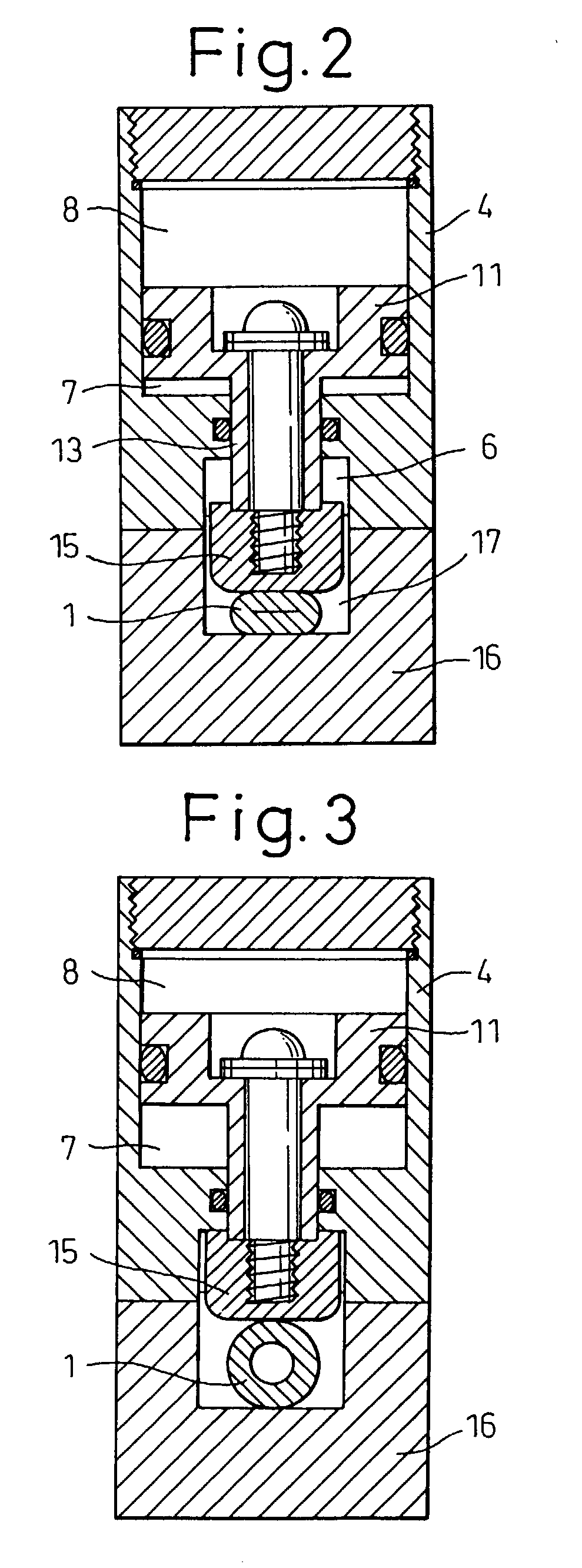
[0050] a pinch valve made of PVDF according to the first invention will be explained below on the basis of FIGS. 1 to 8. Reference numeral 1 designates a tube body which is made of a composition of fluororubber and silicone rubber and in which a fluid flows. The tube body 1 is formed having a predetermined thickness, for example, by adhering and laminating multiple layers of PTFE sheets impregnated with silicone rubber. Although the material of the tube body 1 is a composition of fluororubber and silicone rubber in this embodiment, the tube body may be made of an elastic body, such as EPDM, silicone rubber, fluororubber or a composition of these materials, and it is not especially limited.

[0051] Reference numeral 4 designates a cylinder body which has a cylinder portion 2 with a cylindrical space and to which a disk-like cylinder cover 3 is screwed at the upper end portion of the cylinder body 4 via an O-ring. In the center of the lower surface of the cylinder body 4 are continuousl...

second embodiment

[0061] Next, a reverse operation type pinch valve which is the first invention will be explained below on the basis of FIGS. 9 to 11.

[0062] Reference numeral 35 designates a spring installed in the cylinder portion 2 in a manner such that the upper end surface of the piston 11 and the lower end surface of the cylinder cover 3 contact the spring. Although a single spring 35 is installed in this embodiment, the number of springs may be increased, depending on the urging force required.

[0063] The remaining constitution of the second embodiment is similar to the first embodiment, and thus further explanation will be omitted.

[0064] The operation of the pinch valve of the second embodiment constituted as above and the action as a reverse operating valve is as follows.

[0065] In the condition where the pinch valve is fully closed as shown in FIGS. 9 and 10, if compressed air is supplied into the first space portion 7 from the air port 9, the piston 11 begins to rise in the cylinder portion ...

third embodiment

[0067] Next, a normal operation, type pinch valve which is the first invention will be explained below on the basis of FIGS. 12 to 14.

[0068] In this embodiment, the spring 35 is installed inside the cylinder portion 2, being held by the lower end surface of the piston 11 and the bottom surface of the cylinder portion 2. On the upper region of the cylinder portion 2 is provided a stopper portion 36 over the periphery thereof to set the lowest limit of the piston 11. Although a single spring 35 is installed in this embodiment, the number of springs installed may be increased, depending on the urging force required.

[0069] Since the remaining constitution of the third embodiment is similar to the first embodiment, explanation of the constitution will be omitted.

[0070] The operation of the pinch valve of the third embodiment constituted as above and the action as a normal operating valve is as follows.

[0071] If compressed air is supplied into the second space portion 8 from the air port ...


PUM


Abstract

A pinch valve of the invention comprising an elastic tube body 1, a cylinder body 4 having a cylinder portion 2 and a cylinder cover 3, a piston 11 sliding on the inner periphery of the cylinder body, a pressing piece 15 fixed to a connecting portion 13 suspended from the piston, a body 16 joined to the cylinder body and having a groove 17 receiving the tube body 1, a pair of connecting body carriers 20 engaged with grooves of the body and having a through-hole 26 receiving the tube body 1, a first and a second space portions 8, 7 formed above and under the piston 11, respectively, and a pair of air ports 10, 9 respectively communicating with the first and second space portions 8, 7. The whole pinch valve is made compact in construction.

Description

[0001] The present invention relates to a pinch valve used in a fluid transport pipeline in various industrial fields, such as chemical factories, semiconductor production, food processing, biotechnology or the like, and more particularly, to a pinch valve which is compact and mitigates the damage a tube body suffers during opening and the closing of the valve.[0002] Hitherto, various pinch valves have been proposed, and an example is disclosed in Japanese Examined Utility Model Publication No. 45-3264. According to this publication, as shown in FIGS. 27 and 28, in two upper and lower pistons 41, 42 fitted in a cylinder 40 on a leg member 39 constituted by a leg stand 37 and leg rods 38, the upper piston 41 is fixed to the upper end of a shaft rod 43 and the lower piston 42 is fixed to the upper end of a pipe shaft 44 loosely fitted on the shaft rod 43. On the lower portion of the pipe shaft 44 is provided a wing piece 45 which is fixed to a lower pressing piece 47 via connecting ba...

Claims


Application Information

Patent Timeline
IPC IPC(8): F16K7/06F16K7/07
CPCF16K7/066F16K7/07F16K7/06
Inventor FURUKAWA, SHIGENOBUHAMADA, TAKESHI
Owner ASAHI YUKIZAI KOGYO CO LTD
Why Eureka
Try Eureka