Mud Flap

Inactive Publication Date: 2003-01-16
ANDERSEN BARRY
View PDF0 Cites 10 Cited by
  • Summary
  • Abstract
  • Description
  • Claims
  • Application Information

AI Technical Summary

Benefits of technology

0008] Accordingly, it is an advantage of the invention claimed herein to provide a mud flap which reduces the amount of water and other road debris that is projected off the sides and bottom of the mud flap. It also an advantage of the invention to provide a mud flap which causes water and other road debris passing through its openings to be directed downwardly toward the roadway. It is another advantage of the invention to provide a mud flap which reduces the weight and drag created by the mud flap, thereby increasing fuel economy

Problems solved by technology

While conventional solid mud flaps are effective in deflecting water and roadway debris, they suffer from several disadvantages.
In addition, the solid design of the mud flap prevents air from passing through it, thereby increasing the drag created by the mud flap and decreasing fuel economy.
Similarly, the solid mud flap is heavy and, therefore, decreases fuel economy and payload capacity.
Increased temperature in the area of the tire increases the risk of tire failure.
As a result, the mud flap does little to reduce the drag created by the mud flap, the weight of the mud flap, the rearward displacement of the bottom of the mud flap at high speeds, or increased temperatures in the area of the tire.
The louvers of this mud flap, however, do little to reduce the drag forces created by air resistance because the surface area of the openings is small relativ

Method used


Image

  • Mud Flap
  • Mud Flap
  • Mud Flap

Examples


Embodiment Construction

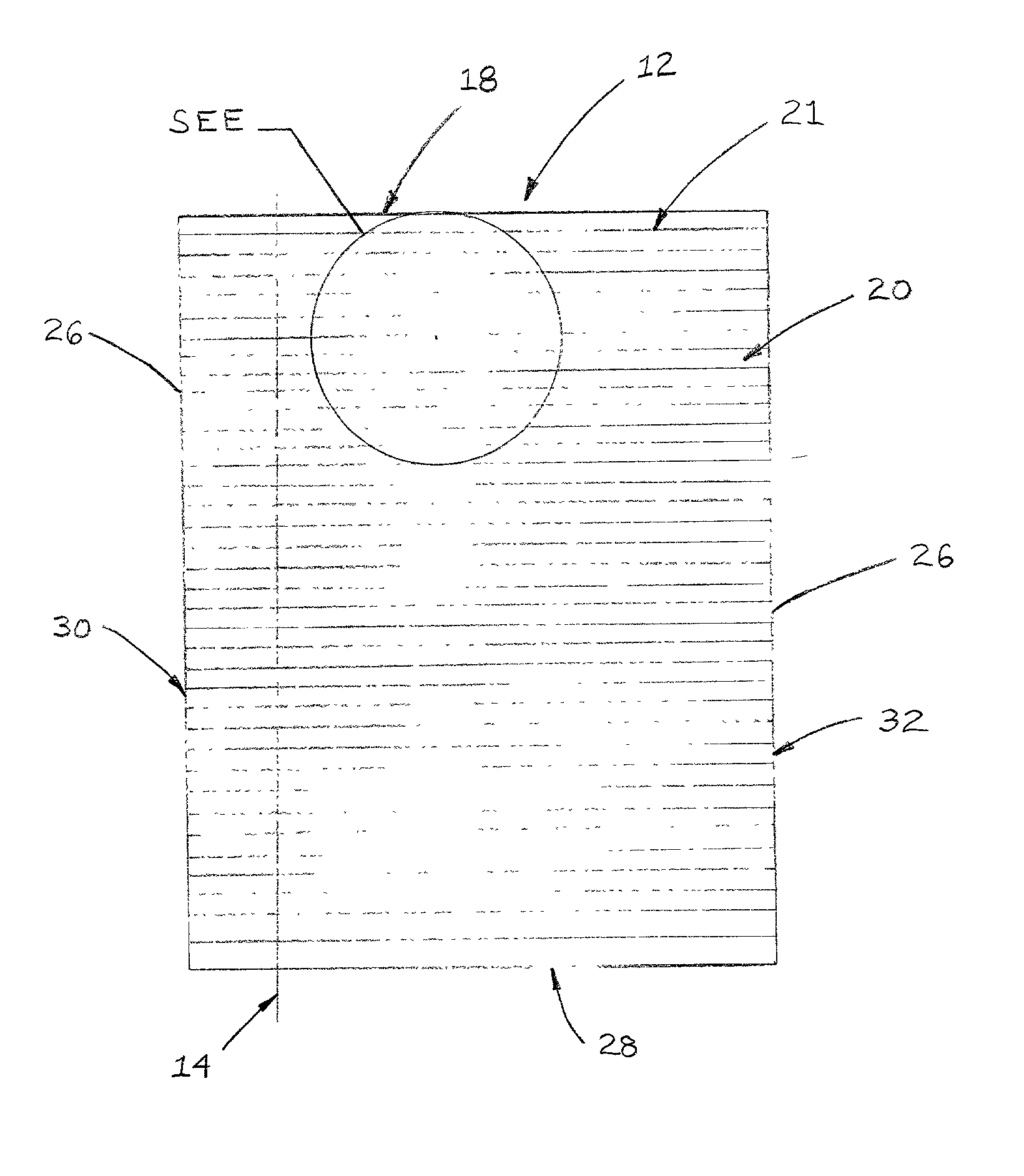
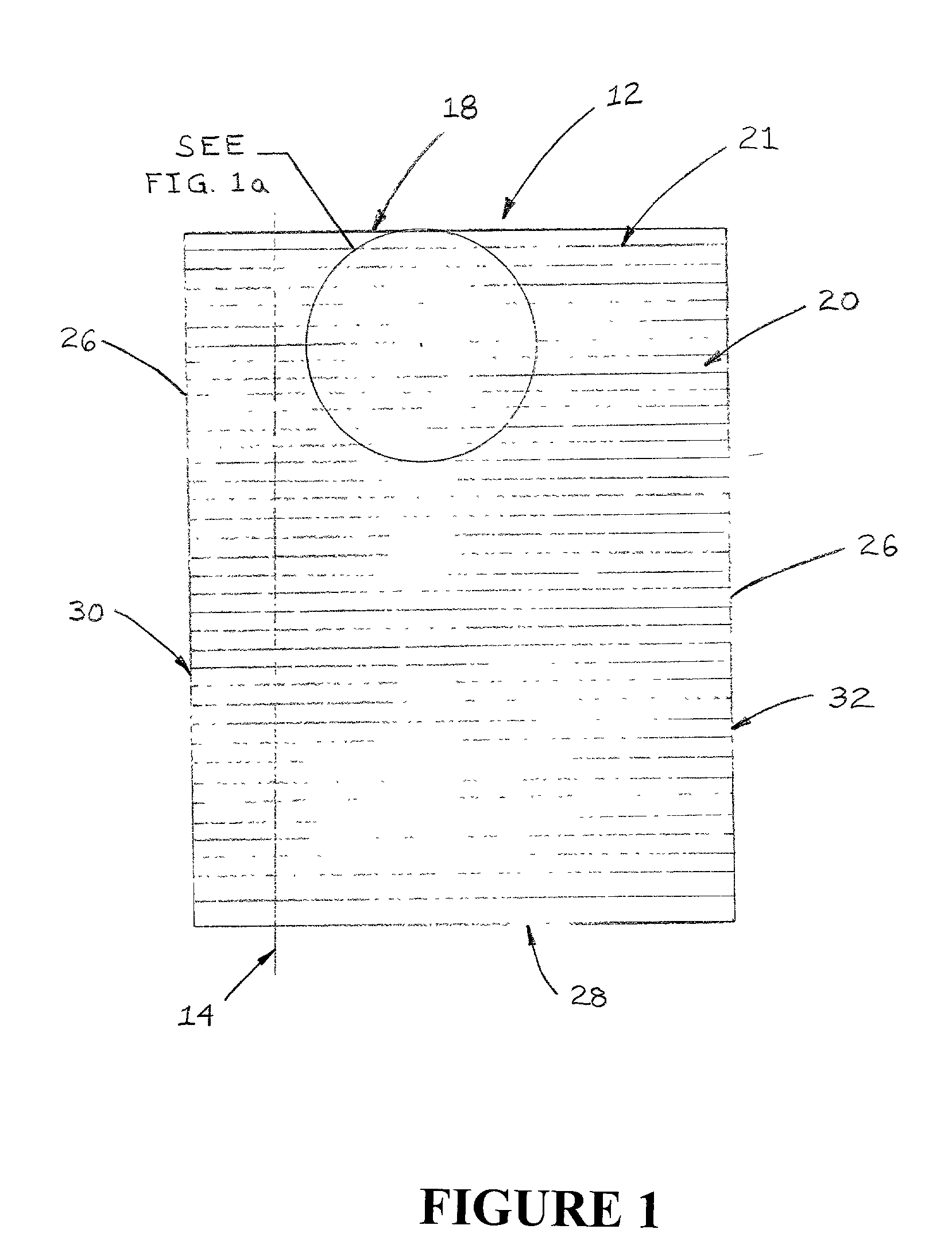
[0022] Referring now to the drawings, the apparatus of the invention is illustrated by FIGS. 1 through 8. The preferred embodiment of the invention is illustrated in FIGS. 1 and 2. As shown in FIGS. 1 and 2, the invention comprises a mud flap for deflecting water and roadway debris propelled by the rotating tires of a moving motor vehicle. The mud flap comprises deflecting panel 12 which may be manufactured using any suitable material conventionally used to make mud flaps such as polypropylene or some other elastomeric or polymeric material. It is also contemplated within the scope of the invention that the deflecting panel may be made from metal. Preferred deflecting panel 12 is preferably manufactured using current plastic molding technology. In the preferred embodiment of the invention, the plastomeric material used to make panel 12 is heated until it becomes a liquid. The liquid may then be introduced into a mold where it is allowed to cool and solidify.

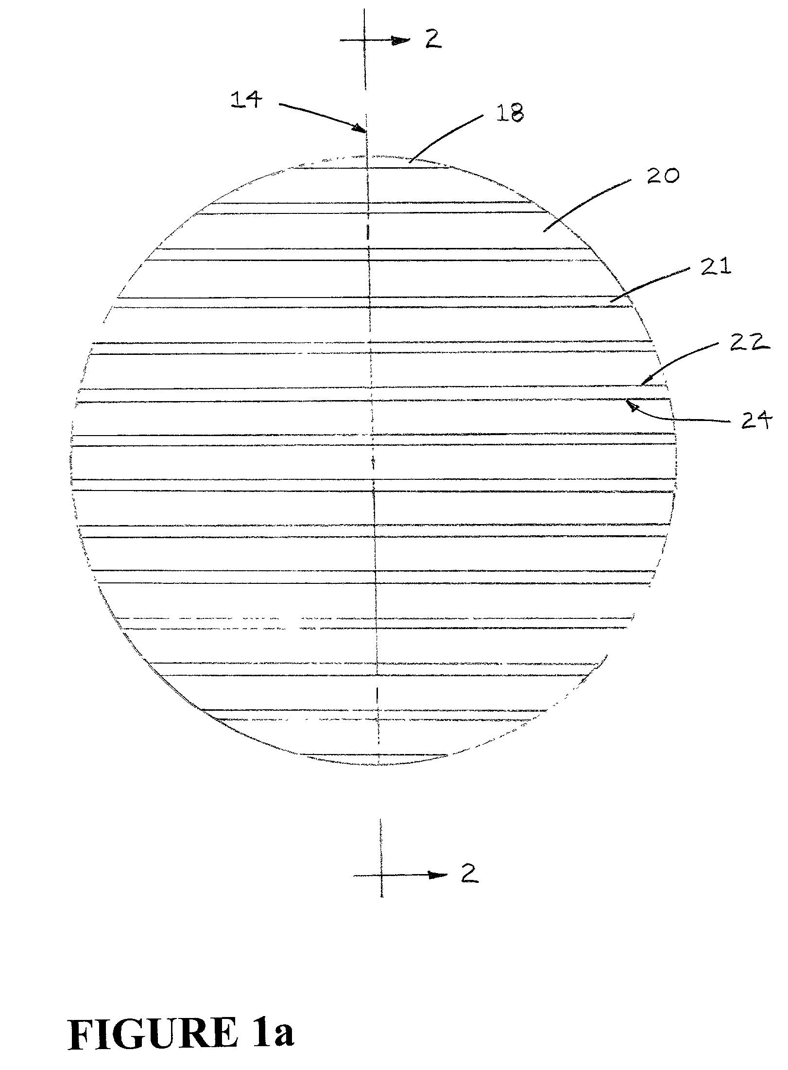
[0023] As illustrated in ...


PUM


Abstract

The invention comprises a mud flap for deflecting water and roadway debris, which is adapted to be attached to a vehicle behind a wheel of the vehicle. According to the invention, the mud flap comprises a deflecting panel having a longitudinal axis, a front face, a top edge, and a plurality of openings in the deflecting panel. Each of the openings is defined by a pair of horizontal members and a pair of vertical members. Each horizontal member has an upper side and a lower side. Each horizontal member is substantially parallel to the top edge, and each vertical member is substantially perpendicular to the top edge. The upper side and lower side of each horizontal member is preferably substantially planar. Each vertical member is also preferably substantially planar. The sum of the areas of the plurality of openings represents at least about 75% of the total surface area of the front face of the deflecting panel. In a preferred embodiment of the invention, the deflecting panel has a thickness of no more than about ¼ (0.25) inch, the lower side of each horizontal member is disposed rearwardly and downwardly at an angle of about 80° from the longitudinal axis, the total area of the openings is about 85% of the surface area of the front face of the deflecting panel, the opposing vertical members are at least about 10 inches apart, and the lower side of each horizontal member is spaced no more than about 1/8 (0.125) inch away from the lower side of the adjacent horizontal member.

Description

[0001] This invention relates generally to mud flaps adapted for use on wheeled vehicles. More particularly, the invention relates to a mud flap having a plurality of openings that are adapted to allow air and small amounts of water and roadway debris to pass therethrough while the flap deflects larger objects away from following traffic.BACKGROUND AND DESCRIPTION OF THE PRIOR ART[0002] Many types of mud flaps have been used for preventing water, mud, rocks and other road debris from being directed rearwardly from a moving wheeled vehicle into the path of following traffic. Typically, mud flaps are substantially rectangular in shape and have a solid deflecting panel. The top edge of each mud flap is conventionally mounted behind a wheel of a vehicle such that the bottom of the mud flap hangs freely near the roadway surface.[0003] While conventional solid mud flaps are effective in deflecting water and roadway debris, they suffer from several disadvantages. First, the solid design of...

Claims


Application Information

Patent Timeline
IPC IPC(8): B62D25/18
CPCB62D25/18
Inventor ANDERSEN, BARRY
Owner ANDERSEN BARRY
Why Eureka
Try Eureka