Catalyst deterioration detecting apparatus and method

a detection apparatus and catalyst technology, applied in the direction of machines/engines, chemical/physical processes, biological material analysis, etc., can solve the problems of reducing the purification capability of catalysts, unable to oxidize hc and co, and discharge all of their oxygen

Inactive Publication Date: 2003-01-23
TOYOTA JIDOSHA KK
View PDF33 Cites 91 Cited by
  • Summary
  • Abstract
  • Description
  • Claims
  • Application Information

AI Technical Summary

Problems solved by technology

Therefore, the purification capability of the catalyst is largely affected by its oxygen storage capability.
Accordingly, when exhaust gas having a shortage of oxygen flows into the catalyst and oxygen continues to be discharged from the catalyst over an extended period of time, the catalyst eventually discharges all of its oxygen such that it is no longer able to oxidize the HC and CO.
Accordingly, when exhaust gas having an excess amount of oxygen flows into the catalyst and oxygen continues to be stored in the catalyst over an extended period of time, the catalyst eventually becomes full of oxygen such that it can no longer reduces the incoming NOx and therefore can no longer purify the exhaust gas.
As a result, unpurified exhaust gas having an excess amount of oxygen flows out downstream of the catalyst during this period.
In this way, when attempting to determine the deterioration of a catalyst by forcefully oscillating the air-fuel ratio back and forth between rich and lean, there is still a possibility of the air-fuel ratio being disturbed in the deterioration determination process, thereby temporarily worsening the exhaust emissions, when only providing a downstream side catalyst further downstream of the catalyst of which determination is being performed.

Method used


Image

  • Catalyst deterioration detecting apparatus and method
  • Catalyst deterioration detecting apparatus and method
  • Catalyst deterioration detecting apparatus and method

Examples


exemplary embodiment 1

[0039] Exemplary Embodiment 1

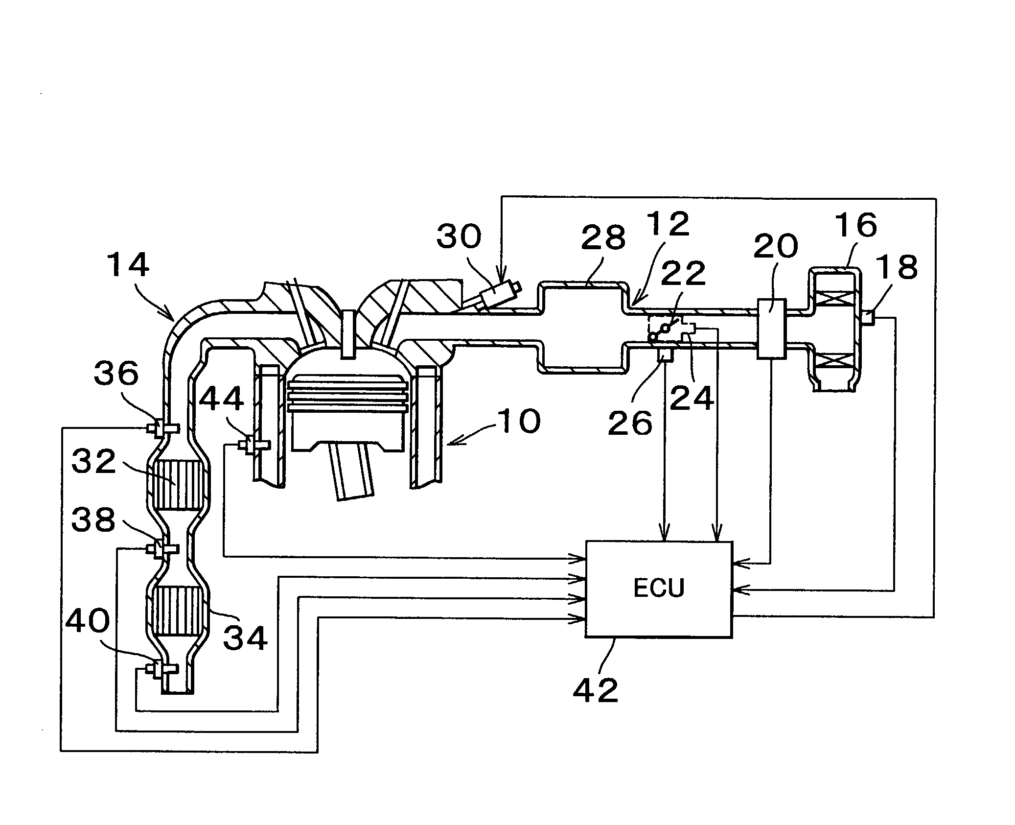
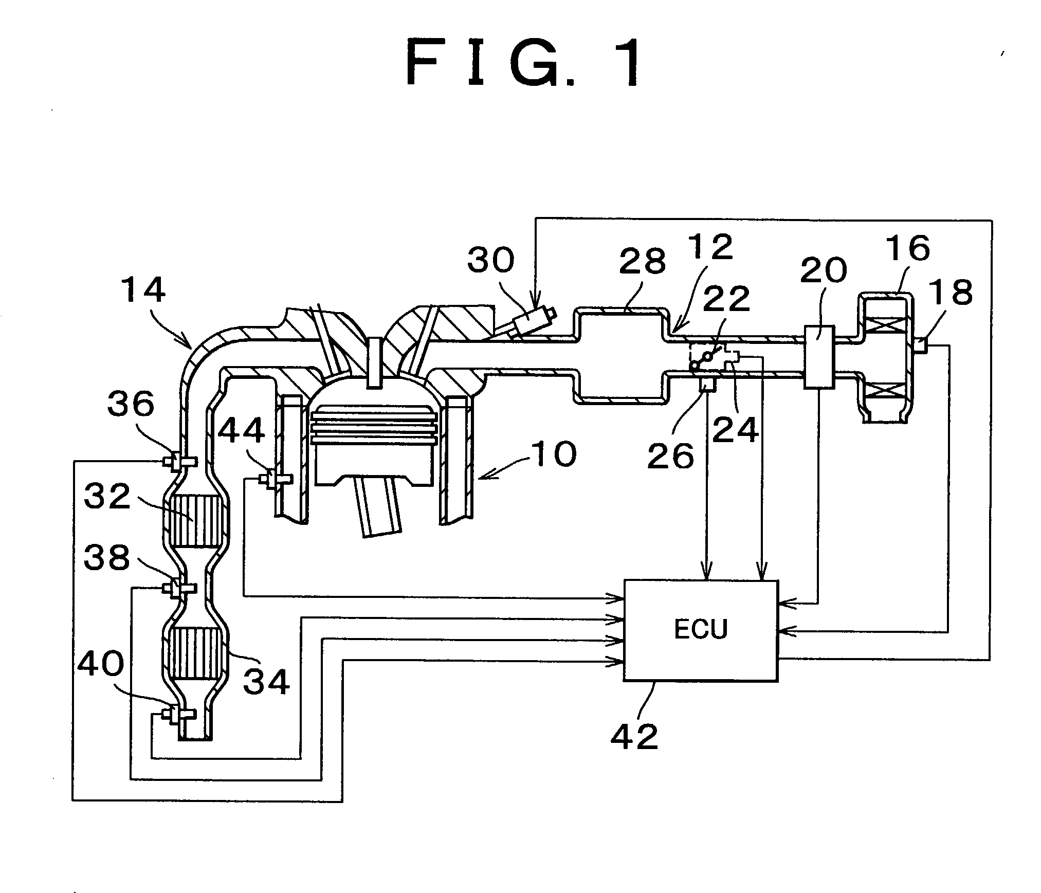
[0040] FIG. 1 is a drawing to explain an internal combustion engine 10 in which is mounted a catalyst deterioration detecting apparatus, as well as the surrounding structure thereof, according to a first exemplary embodiment of the invention. An intake passage 12 and an exhaust passage 14 are communicated with the internal combustion engine 10. The intake passage 12 is provided with an air filter 16 on the upstream side end portion. An intake air temperature sensor 18 that detects an intake air temperature THA (i.e., outside air temperature) is mounted in the air filter 16.

[0041] An airflow meter 20 is disposed downstream of the air filter 16. The airflow meter 20 is a sensor that detects an intake air amount Ga which flows through the intake passage 12. A throttle valve 22 is provided downstream of the airflow meter 20. Near the throttle valve 22 are disposed a throttle sensor 24 that detects a throttle opening TA and an idle switch 26 which turns on wh...

exemplary embodiment 2

[0122] Exemplary Embodiment 2

[0123] Next, a second exemplary embodiment of the invention will be described with reference to FIG. 7. In the figure, elements in exemplary Embodiment 2 that are the same as those in exemplary Embodiment 1 are denoted by the same reference numerals that they are denoted by in exemplary Embodiment 1, and redundant explanations thereof will be omitted. The catalyst deterioration detecting apparatus according to exemplary Embodiment 2 is the same as the apparatus in exemplary Embodiment 1 except in that the ECU 42 performs the routine shown in FIG. 7 in place of the aforementioned routine shown in FIG. 5. The apparatus according to exemplary Embodiment 1 determines the deterioration state of the upstream side catalyst 32 based on a single oxygen storage capacity OSC. In contrast, the catalyst deterioration detecting apparatus in exemplary Embodiment 2 determines whether the upstream side catalyst 32 is deteriorating based on a plurality of oxygen storage c...

exemplary embodiment 3

[0131] Exemplary Embodiment 3

[0132] Next, a third exemplary exemplary embodiment of the invention will be described with reference to FIG. 8. In the figure, the elements in exemplary Embodiment 3 that are the same as those in exemplary Embodiment 1 are denoted by the same reference numerals that they are denoted by in exemplary Embodiment 1, and redundant explanations thereof will be omitted. The catalyst deterioration detecting apparatus according to exemplary Embodiment 3 is the same as the apparatuses in exemplary Embodiments 1 and 2 except in that the ECU 42 performs the routine shown in FIG. 8 in place of the aforementioned routine shown in FIG. 5 or FIG. 7. The apparatus according to exemplary Embodiment 2 determines the deterioration state of the upstream side catalyst 32 by a majority of a plurality of temporary determinations that are based on specific oxygen storage capacities OSC. In contrast, the catalyst deterioration detecting apparatus in exemplary Embodiment 3 determ...


PUM

PropertyMeasurementUnit
output voltage V02aaaaaaaaaa
oxygen concentrationaaaaaaaaaa

Abstract

An upstream side catalyst and a downstream side catalyst are disposed in an exhaust passage. A first oxygen sensor is disposed between these two catalysts and a second oxygen sensor is disposed downstream of the downstream side catalyst. The air-fuel ratio is forcibly oscillated and the oxygen storage capacity of the upstream side catalyst is detected. Deterioration of the upstream side catalyst is then detected based on whether this oxygen storage capacity is larger than a predetermined value. The forced oscillation of the air-fuel ratio is performed only when the oxygen storage state of the downstream side catalyst is appropriate.

Description

INCORPORATION BY REFERENCE[0001] The disclosure of Japanese Patent Application No. 2001-218661 filed on Jul. 18, 2001 and No. 2001-285885 filed on Sep. 19, 2001 including the specification, drawings and abstract are incorporated herein by reference in their entireties.[0002] 1. Field of the Invention[0003] The invention relates generally to a catalyst deterioration detecting apparatus that uses a catalyst having an oxygen storage capability. More specifically, the invention relates to a catalyst deterioration detecting apparatus that detects deterioration of a catalyst that purifies exhaust gas of an internal combustion engine.[0004] 2. Description of Related Art[0005] A catalyst used to purify exhaust gas is disposed in an exhaust passage of an internal combustion engine for a vehicle. This catalyst is capable of storing an appropriate amount of oxygen. When the exhaust gas that flows into this catalyst contains unburned components such as hydrocarbons HC and carbon monoxide CO and...

Claims


Application Information

Patent Timeline
Patent Type & Authority Applications(United States)
IPC IPC(8): B01D53/94F01N11/00F02D41/02F02D41/14F02D41/22
CPCB01D53/9495F01N11/007F01N2550/02F02D41/0295F02D41/1408F02D41/22Y10T436/25875F02D2200/0816Y02T10/40Y02T10/47Y10T436/20Y10T436/208339F02D2200/0814
Inventor UCHIDA, TAKAHIROSAWADA, HIROSHINAGAI, TOSHINARIKATAYAMA, AKIHIROKUZE, YASUHIROKATO, NAOTO
Owner TOYOTA JIDOSHA KK
Why Eureka
Try Eureka