Dynamic splitting of connecting rods

a technology of connecting rods and dynamic splitting, which is applied in the direction of mechanical equipment, engine components, manufacturing tools, etc., can solve the problems of imposing a significant increase in manufacturing costs, eliminating the economic benefit of the near-network shape process, and rods and caps will no longer fit perfectly back together

Inactive Publication Date: 2003-01-30
HOFFMANN GOTTFRIED
View PDF24 Cites 14 Cited by
  • Summary
  • Abstract
  • Description
  • Claims
  • Application Information

AI Technical Summary

Problems solved by technology

The large amount of assembly and disassembly that are required to complete a two-piece connecting rod imposes a significant increase in manufacturing costs.
If machining operations were utilized to separate the rod and the cap, additional machining operations similar to those described above with respect to two-piece connecting rods would be required, thereby eliminating the economic benefit of the near net shape processes.
If any plastic deformation occurs to either the rod or the cap portion during the splitting process, the rod and cap will no longer fit perfectly back together and the dimensions and roundness of the bore will be compromised.
The powder forging process allows for a notch to be produced in the preform that is partially closed during the subsequent forging operation, thereby producing an internal crack that provides a very high stress concentration.
One drawback to using highly brittle materials however is that the service life of a connecting rod generally decreases as the brittleness of the material is increased.
While resonance-fatigue techniques have successfully improved on fracture splitting techniques, resonance-fatigue techniques are extremely complicated, and require computational modeling and specialized part fixturing to guarantee success.
The additional research and capital costs associated with developing the computational models and the new part fixtures and loading stations may preclude some manufacturers from making connecting rods using resonance-fatigue techniques.

Method used


Image

  • Dynamic splitting of connecting rods
  • Dynamic splitting of connecting rods
  • Dynamic splitting of connecting rods

Examples


Embodiment Construction

[0021] Before describing the invention in detail, it will be helpful to introduce certain metallurgical concepts and equations to facilitate a more complete understanding of the invention.

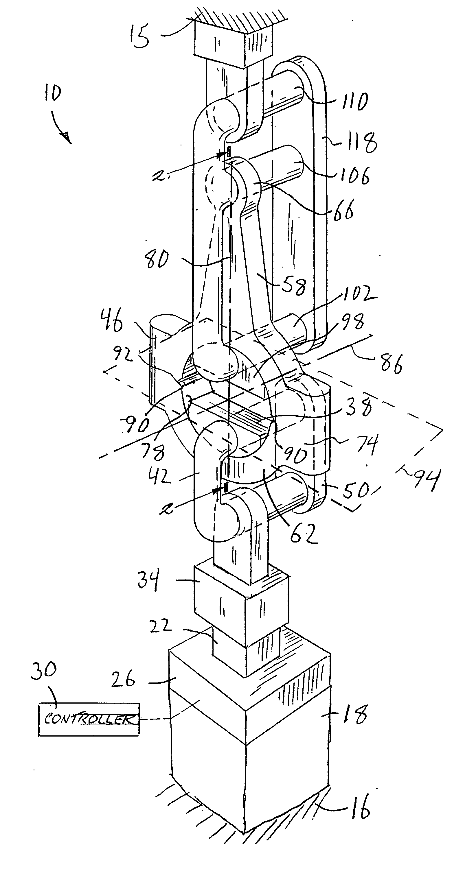
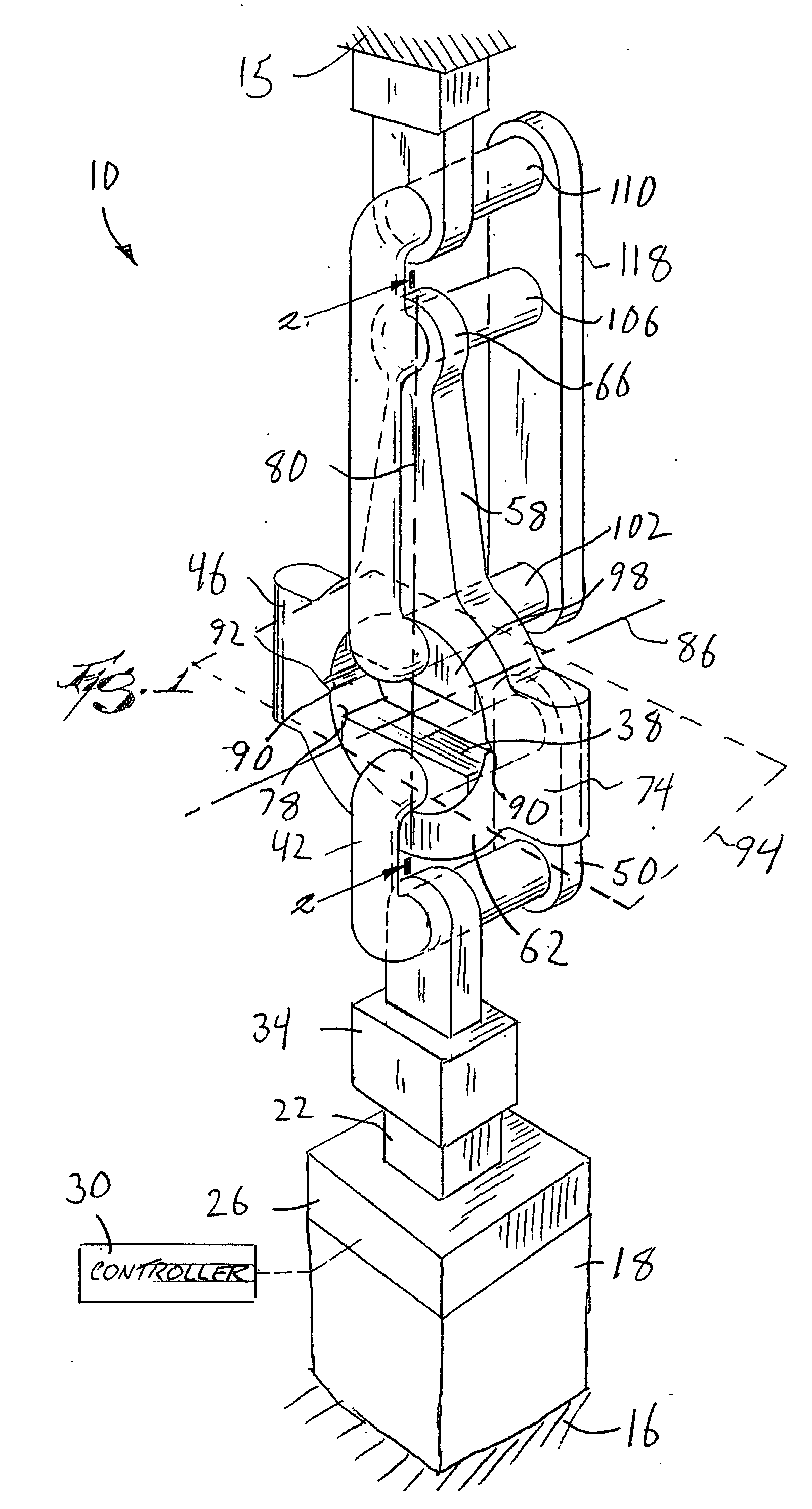
[0022] The present invention deals with dynamically loading and fatigue fracturing substantially any structural part that is fractured into two or more separate pieces, and is then reassembled into a single assembly having substantially the same shape and dimensions as the original, non-fractured part. One of the most useful applications for the fatigue fracturing method of the present invention relates to connecting rods for piston cylinder devices, such as those discussed above in the Background.

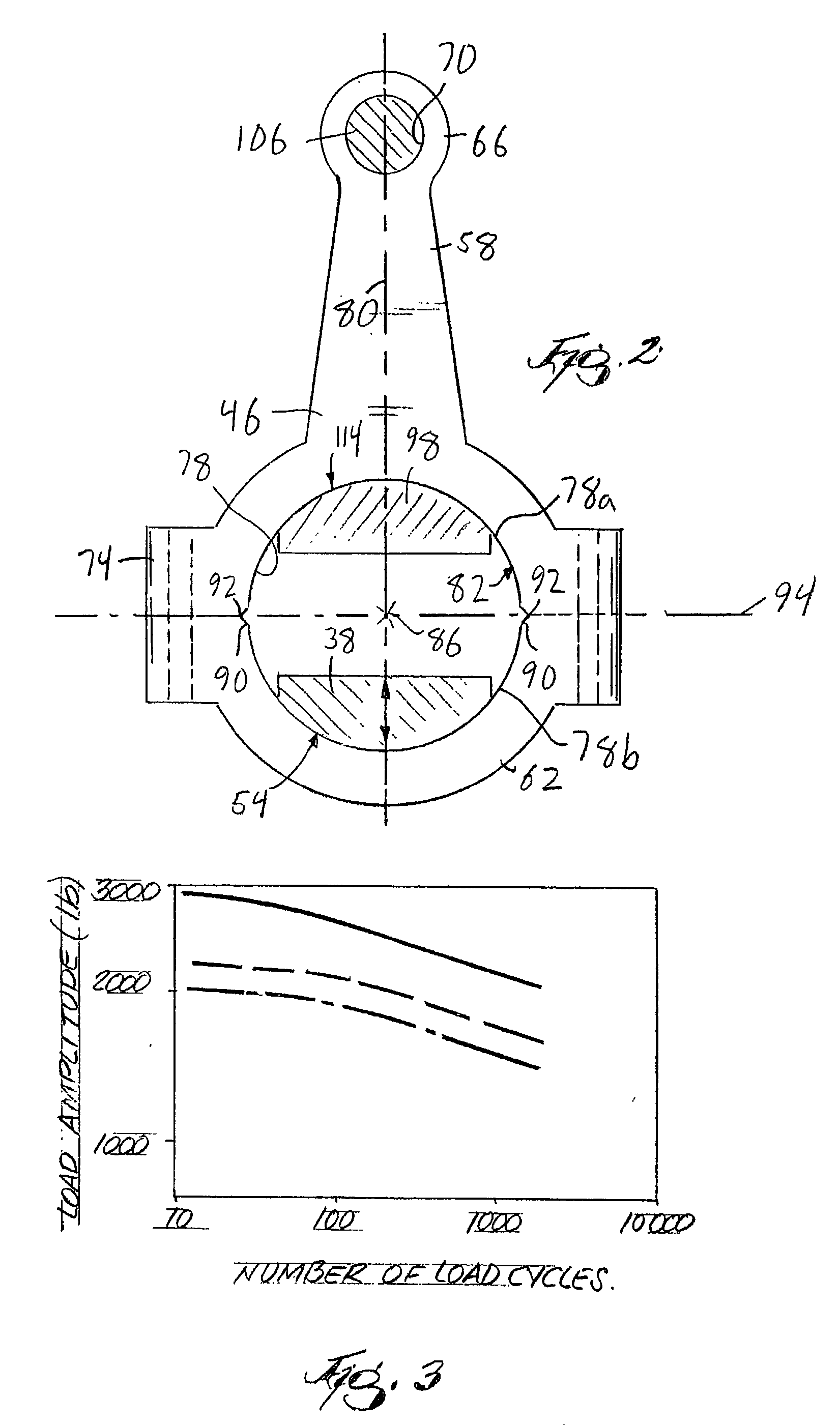
[0023] As discussed above, fracture mechanics principles suggest that substantially any solid material will break in a brittle fashion when a material crack having a certain length is subjected to a certain tensile stress. The crack length and tensile stress required for brittle fracture of a given part a...


PUM

PropertyMeasurementUnit
frequencyaaaaaaaaaa
oscillation frequencyaaaaaaaaaa
fracture planeaaaaaaaaaa

Abstract

A method for separating a one-piece connecting rod into a cap and a rod includes forming diametrically opposed notches in the connecting rod bore to define a fracture plane that is substantially parallel to the bore central axis. One portion of the connecting rod is clamped to hold it substantially fixed with respect to the other portion of the connecting rod. An oscillatory load is applied to the other of the portions in a direction that is substantially perpendicular to the fracture plane to develop fatigue cracks in the vicinity of the notches. The fatigue cracks are propagated through the connecting rod by the oscillatory load until the connecting rod is separated into the cap and the rod. An apparatus for performing the method is also disclosed.

Description

[0001] The present Application claims priority under 35 U.S.C. .sctn.119 to a Provisional Patent Application Serial No. 60 / 308,324, filed on Jul. 26, 2001.[0002] 1. Field of the Invention[0003] The invention relates to methods and apparatus for splitting and fracturing objects, and more particularly to methods and apparatus for splitting connecting rods.[0004] 2. Related Prior Art[0005] Connecting rods for various types of piston-cylinder devices such as internal combustion engines, compressors, and the like are primarily manufactured using one of the following three material / process combinations: ductile iron alloy castings, wrought steel die forgings, and powdered metal forgings. Improvements to the each of the above processes has lead to "near net shape" production of connecting rods, which has reduced the amount of required finish machining drastically, and resulted in remarkable manufacturing cost reductions.[0006] Substantially all connecting rods include a large end, and a sm...

Claims


Application Information

Patent Timeline
Patent Type & Authority Applications(United States)
IPC IPC(8): B23D31/00
CPCB23D31/003Y10T29/49792Y10T29/49288Y10T29/4979
Inventor HOFFMANN, GOTTFRIED
Owner HOFFMANN GOTTFRIED
Why Eureka
Try Eureka