Optical lens for improved vision under conditions of low or poor illumination

Inactive Publication Date: 2003-01-30
STONE ROBERT F
View PDF0 Cites 23 Cited by
  • Summary
  • Abstract
  • Description
  • Claims
  • Application Information

AI Technical Summary

Problems solved by technology

Many people, whether they require vision correction or not, often experience reduced visual acuity (poor vision) at night.
Additionally, the spherical and oblique aberrations result in an increased image size on the retina of the eye, which, in turn, stimulates the process of accommodation.
Under low light conditions, however, the lack of focus caused by the aberrations stimulates the accommod

Method used


Image

  • Optical lens for improved vision under conditions of low or poor illumination
  • Optical lens for improved vision under conditions of low or poor illumination

Examples


Example

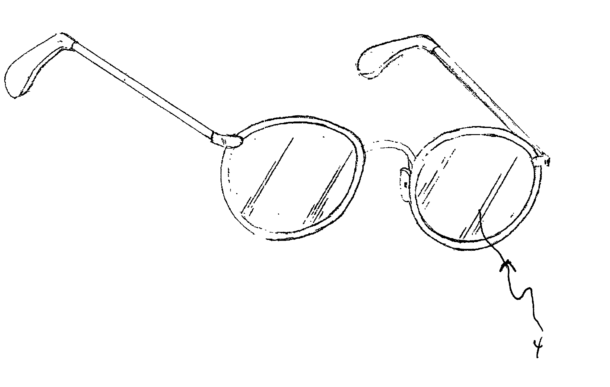
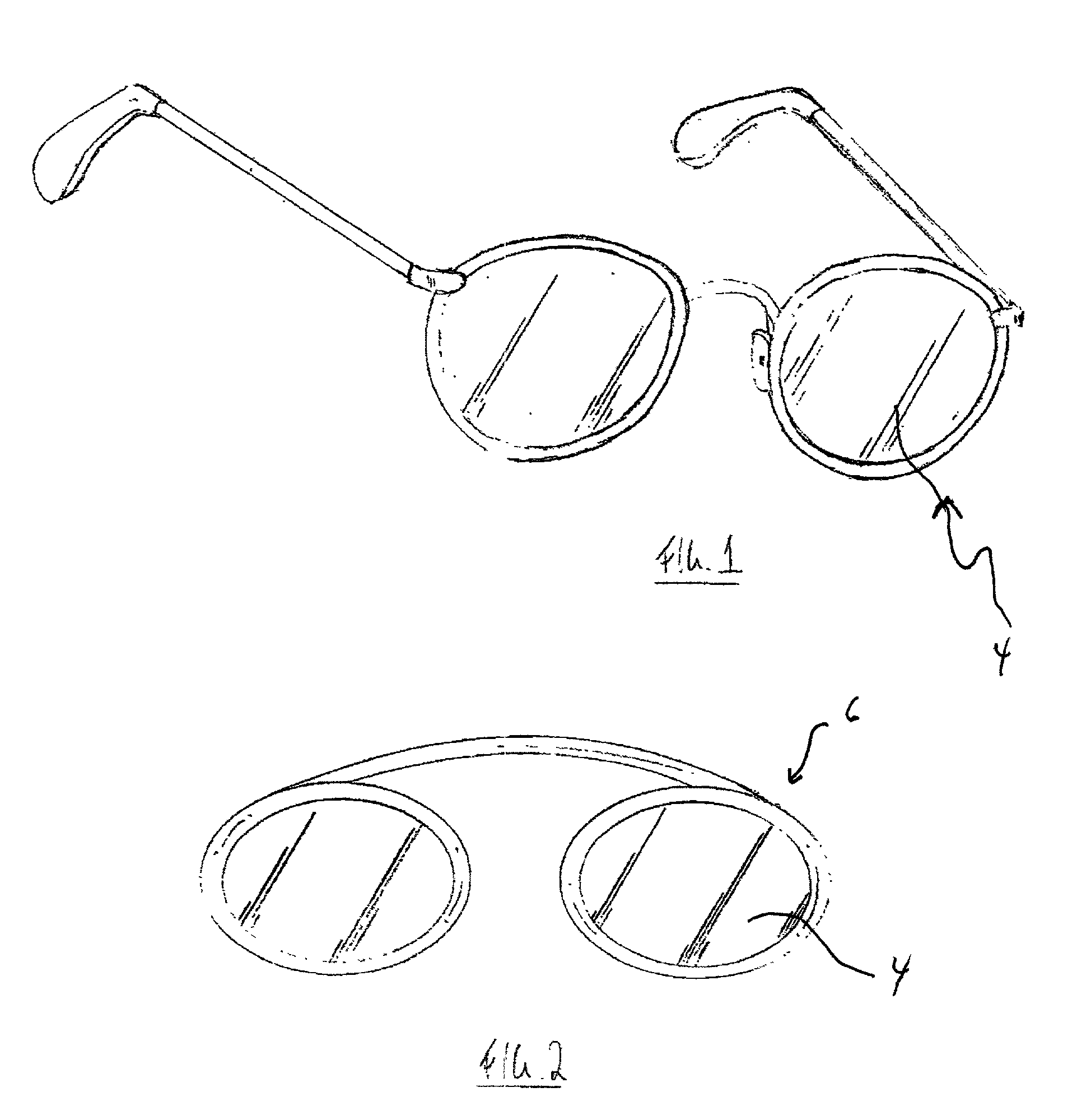
[0021] Referring to FIG. 1, there is seen a typical pair of spectacles incorporating the lenses 4 of the present invention with the lens having a shape corresponding to the eye glass frames selected by a user.

[0022] As described above, the lenses 4 have a power of from about minus 0.12 to minus 1.00 diopters.

[0023] The use of such lenses during low light and nighttime driving, ambulating, equipment operation, and the like, results in improved acuity and vision and adequately adjusts for the refractive shift often experienced when attempting to see under conditions of poor illumination.

[0024] The applicant herein and through his own work in the field, has found that although the lens power necessary to achieve the benefit of the present invention may vary based on the user, such range is not a function of a user's pre-existing prescription and is most typically achieved with a lens 4 having a power of minus 0.50 diopters.

[0025] Referring to FIG. 2, there is seen an alternate embodime...


PUM


Abstract

An eyeglass lens having a power of from about a minus 0.12 to about minus 1.00 diopters (and preferably minus 0.50 diopters) that is particularly beneficial and improves vision of a user under night or other low-light conditions. The lens may be incorporated in a pair of eyeglass frames and may be used by users without corrective eyewear or in a pair of clip-on" frames for use by a user already requiring corrective eyewear.

Description

[0001] 1. Field of Invention[0002] The present invention is related generally to vision wear such as eyeglasses, sunglasses, or eyeglass "clip-ons", and the like; and more particularly to an optical lens for use in enhancing nighttime vision and for use during nighttime driving.[0003] 2. Description of Prior Art[0004] Many people, whether they require vision correction or not, often experience reduced visual acuity (poor vision) at night. This phenomenon, called night myopia, results from physical changes in the eye resulting from the low light conditions experienced at night. The physical manifestation of night myopia is blurred vision under these conditions of reduced light.[0005] The normal human eye in "seeing" an object is, in reality, viewing the light rays reflected off an object which rays pass through the pupil of the eye and are focused on the retina by the operation of the eye's cornea and lens.[0006] The source of the above described myopia is found in the fact that when...

Claims


Application Information

Patent Timeline
IPC IPC(8): G02C7/02
CPCG02C7/02
Inventor STONE, ROBERT F.
Owner STONE ROBERT F
Why Eureka
Try Eureka