

Swivel/quick release device for tow rope
- Summary
- Abstract
- Description
- Claims
- Application Information
AI Technical Summary
Benefits of technology
Problems solved by technology
Method used
Image

Examples
Embodiment Construction
[0013] In the drawings:
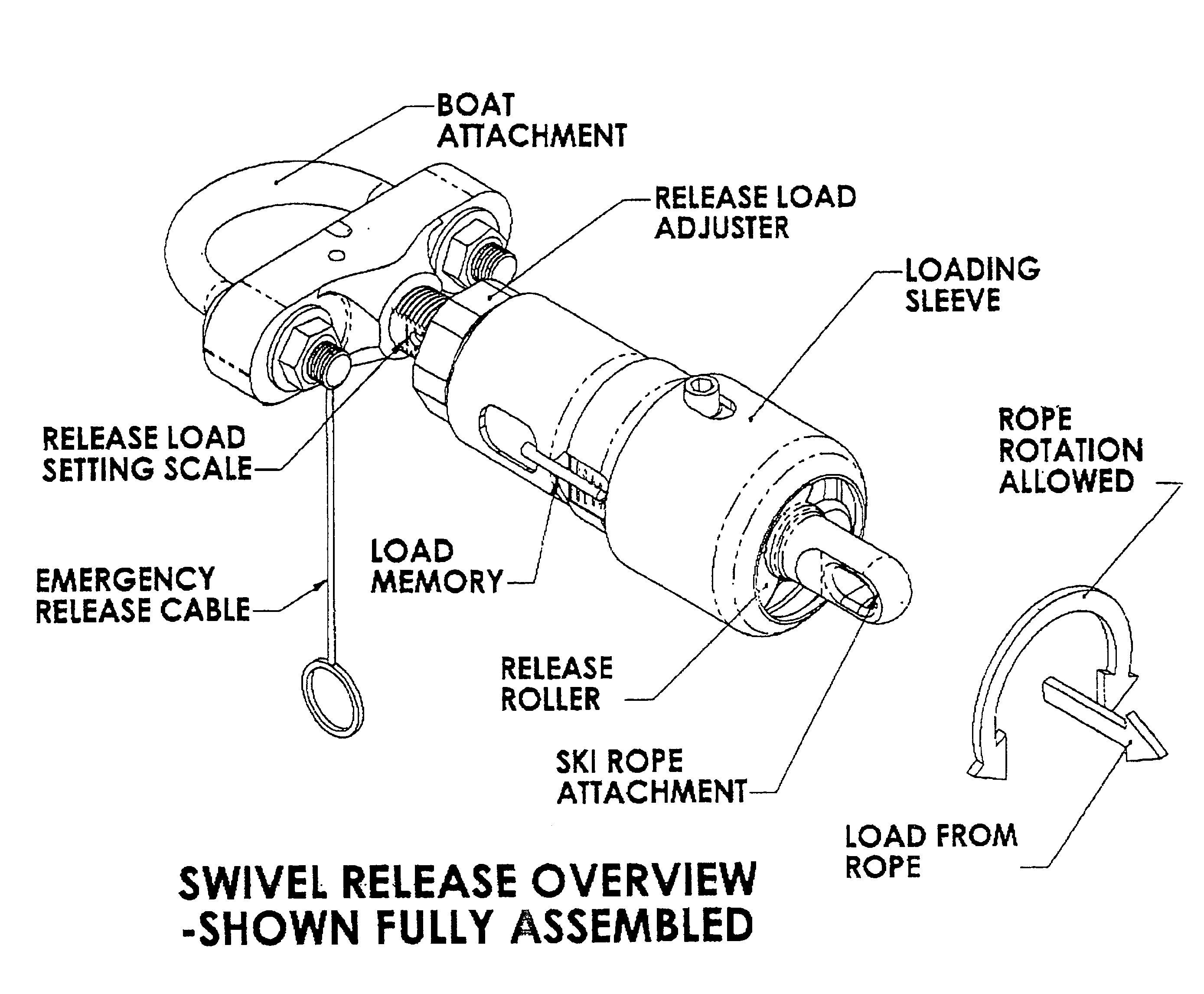
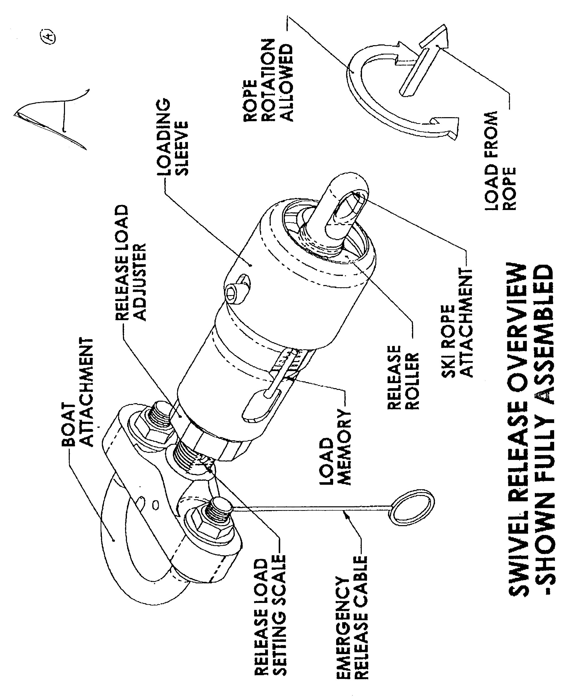
[0014] FIG. A is a perspective view of the swivel / quick release of this invention, shown fully assembled.
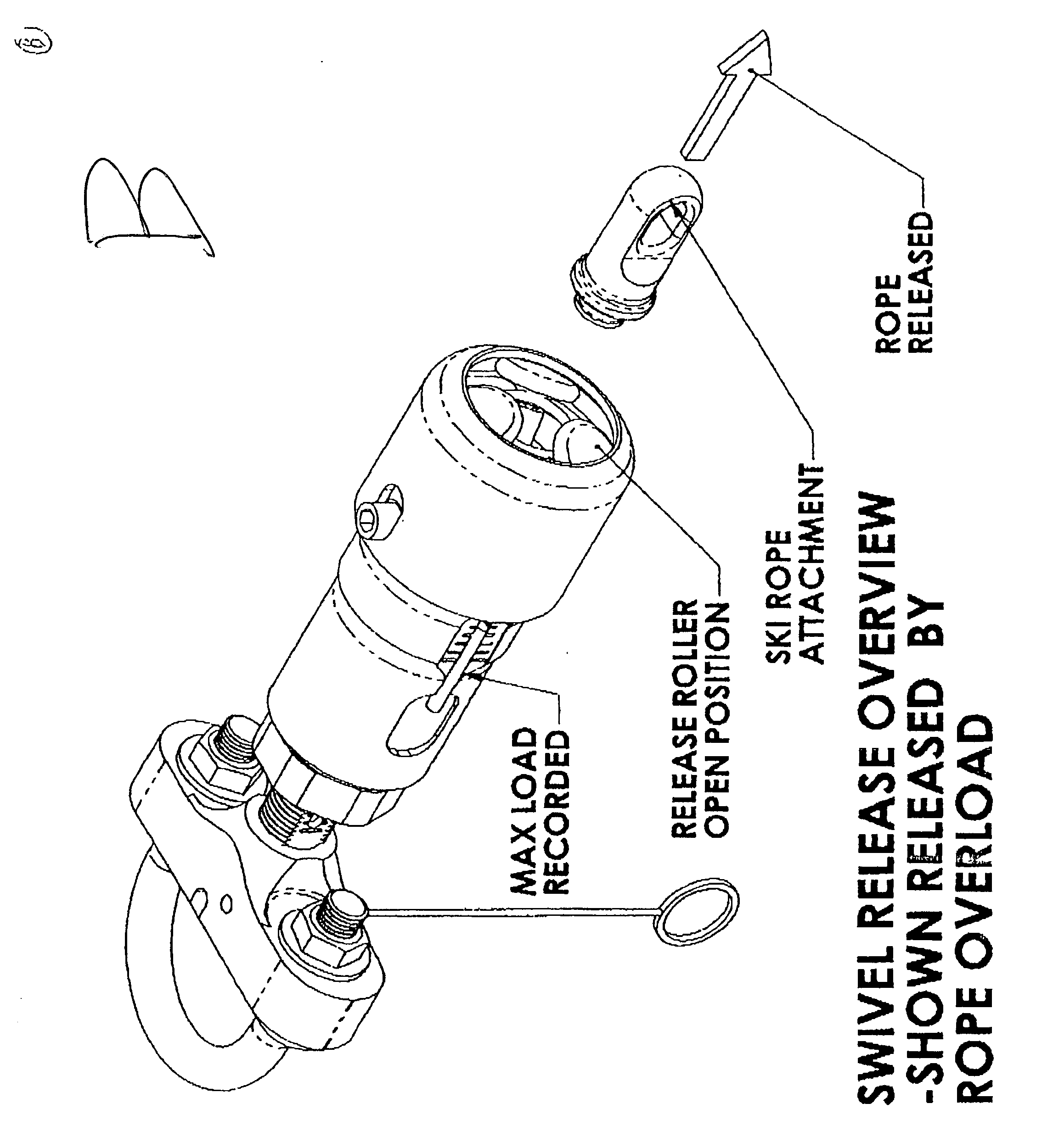
[0015] FIG. B is a perspective view of the device of FIG. 1 with rope attachment released by rope overload.
[0016] FIG. C is a longitudinal section through the device of FIG. 1, with no load applied.
[0017] FIG. D is a sectional view similar to FIG. 1, but with the rope under tension but at less than release load.
[0018] FIG. E is similar to FIG. 4 with the device shown at release load.
[0019] FIG. F is similar to FIG. 5, but where the release occurs manually rather than by loading.
[0020] FIG. G is similar to FIG. 3 with the device adjusted to release at a lighter load.
[0021] FIG. H is a partial section perspective view of the device in the state shown in FIG. C.
[0022] FIG. I is a partial section perspective view of the device in the state shown in FIG. D.
[0023] FIG. J is a partial section perspective view of the device of FIG. E, but prior to release of the ro...
PUM
 Abstract
Description
Claims
Application Information