Holding mechanism of rotating member

a technology of rotating members and holding mechanisms, which is applied in the direction of couplings, manufacturing tools, transportation and packaging, etc., can solve the problems of insufficient strength, high cost of cutting work of cut surfaces, and limited use condition and design of holding mechanisms 120

Inactive Publication Date: 2003-02-06
NIFCO INC
View PDF3 Cites 0 Cited by
  • Summary
  • Abstract
  • Description
  • Claims
  • Application Information

AI Technical Summary

Problems solved by technology

However, since the rotating shaft 104 is made of the resin, in case the holding mechanism 100 is used as, for example, a stand for a deck board, there has been a defect such that the strength is not sufficient.
On the other hand, in or

Method used


Image

  • Holding mechanism of rotating member
  • Holding mechanism of rotating member
  • Holding mechanism of rotating member

Examples


Embodiment Construction

[0034] A holding mechanism of a rotating member according to the present invention will be described in detail with reference to an embodiment hereunder.

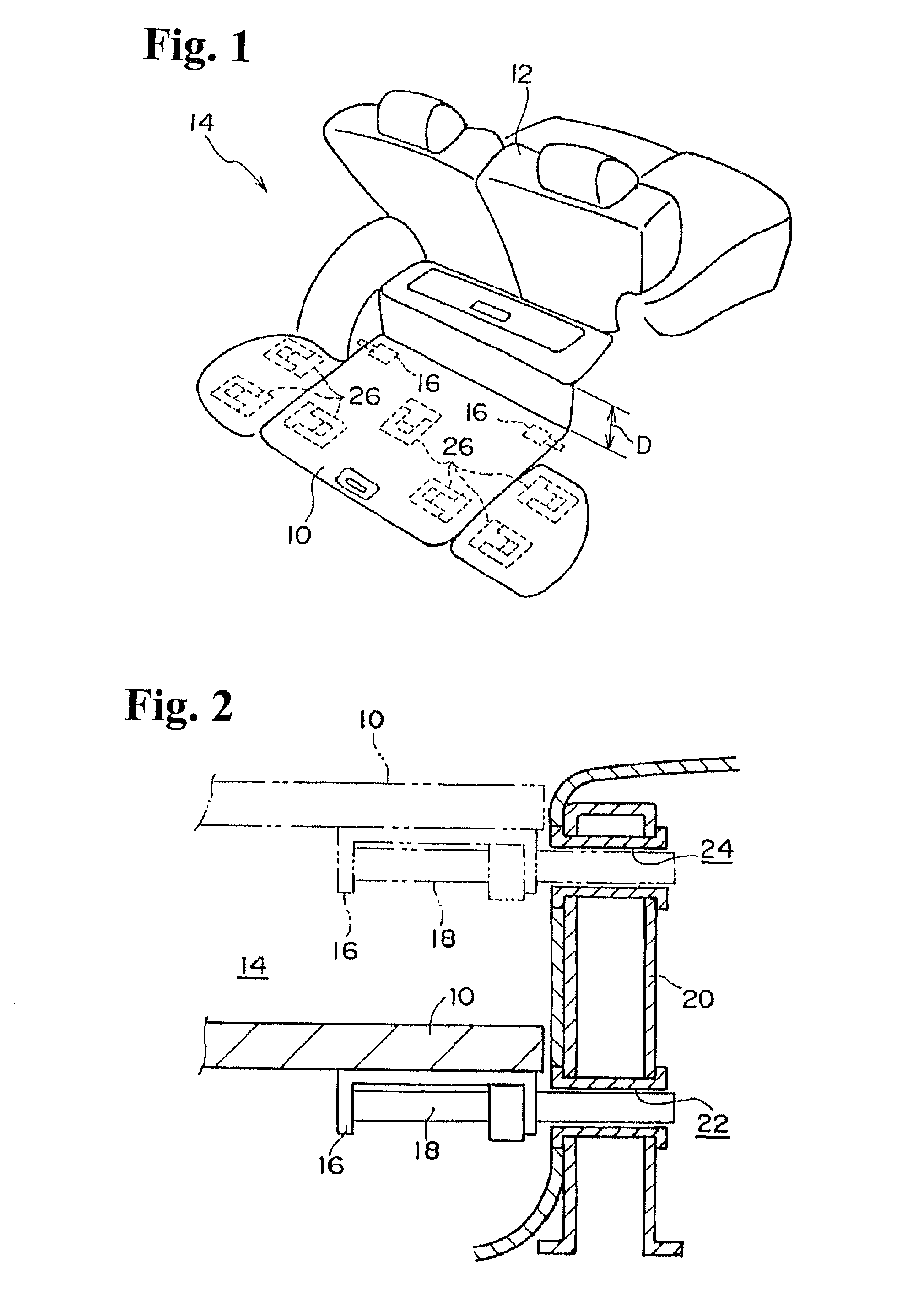
[0035] First, a using state of a deck board to which the holding mechanism of the rotating member is applied will be explained. As shown in FIGS. 1 and 2, a deck board 10 is used in a baggage room 14 located in the rear of seats 12 of a wagon, and is rotatably held by inserting a shaft 18, which is inserted into bearing members 16 attached to both ends of the baggage room 14, into lower through-holes 22 or upper through-holes 24 of brackets 20 disposed on side surfaces of the baggage room 14.

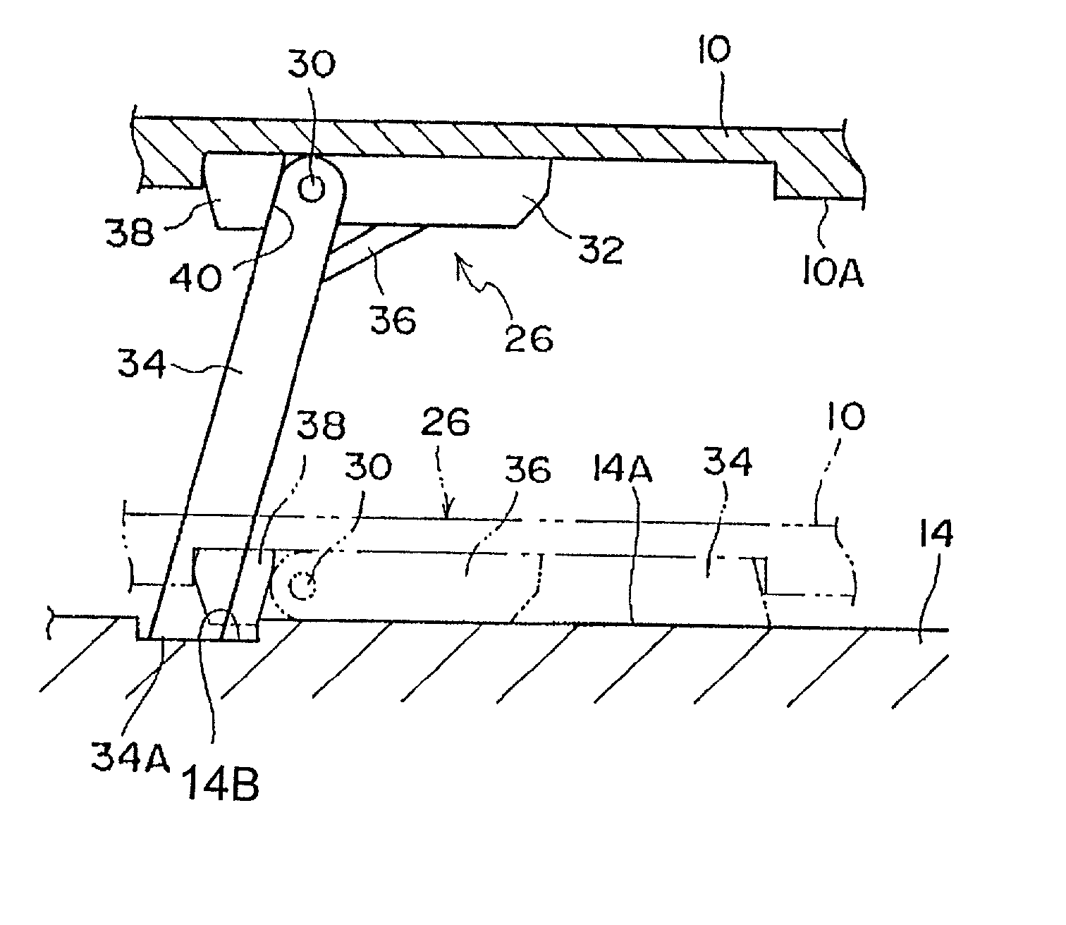
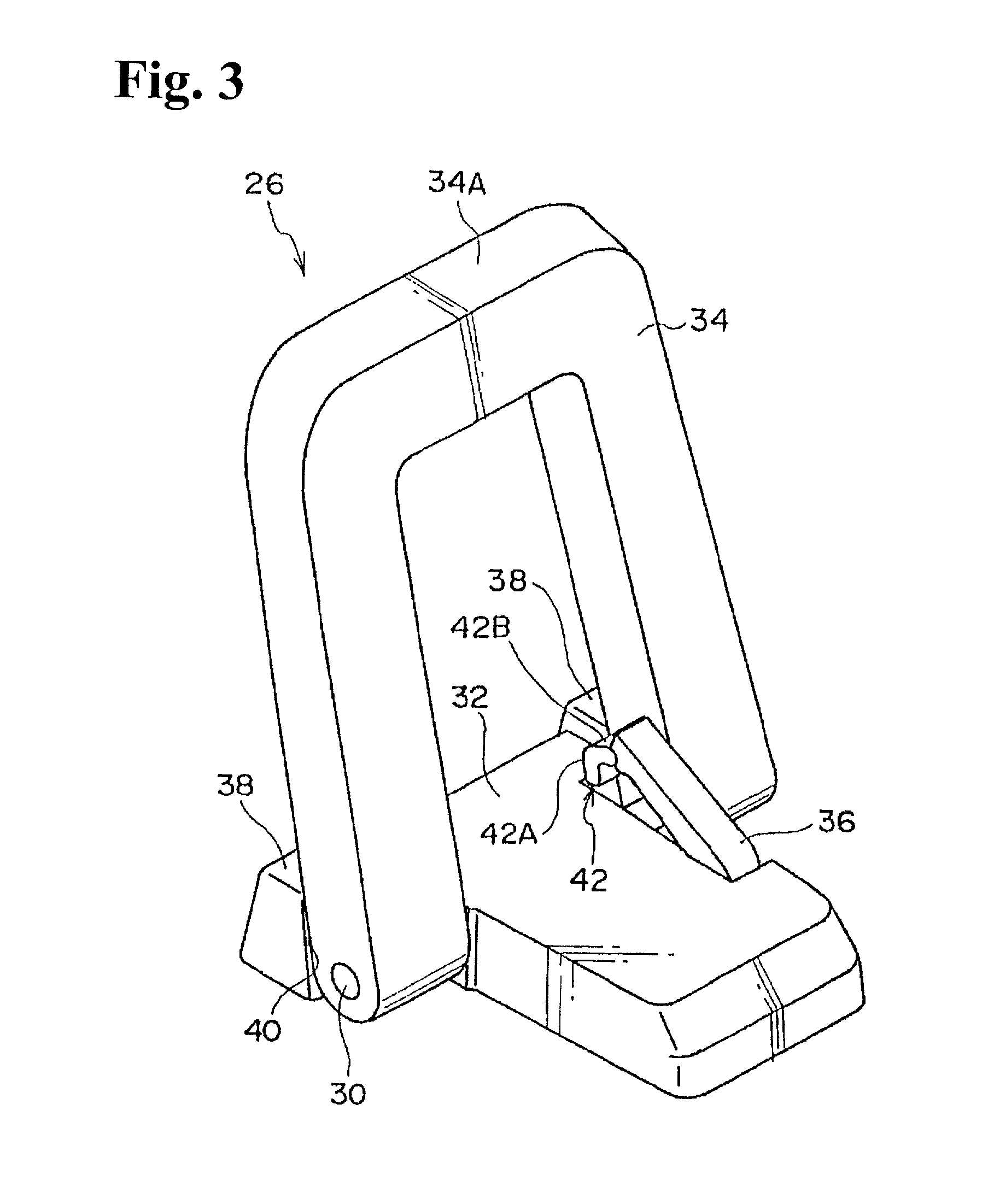
[0036] In other words, the height of the deck board 10 is changed by changing the inserting position of the shaft 18. Incidentally, stands 26 are provided under a lower surface of the deck board 10 to hold the same horizontally. In case the deck board 10 is placed in a lower position, the stands 26 are fallen down, and in case the deck board 10 ...


PUM


Abstract

A holding mechanism for a rotating member includes a main member having a rotating shaft; a leg member rotationally attached to the rotating shaft to change from a housed state to a stand-up state; and a stopper formed on the main member at a position away from the rotating shaft. The stopper holds the stand-up state of the leg member. The leg member in the stand-up state can be rotated to the housed state by pushing the leg member.

Description

BACKGROUND OF THE INVENTION AND RELATED ART STATEMENT[0001] The invention relates to a holding mechanism of a rotating member.[0002] Heretofore, there has been known a mechanism wherein a leg member rotated around a rotating shaft is transferred between a stand-up state and a housed (lying-down) state. In such a mechanism, there has been proposed a holding mechanism for holding a rotating member, such as a leg member, in the stand-up state.[0003] For example, as shown in FIG. 10, in a holding mechanism 100, a leg member 106 is rotatably supported around a rotating shaft 104 by a main member 102. When the leg member 106 is rotated from the housed state (solid line portion) to the stand-up state (two-dotted chain line portion), a cut surface 104A of the rotating shaft 104 abuts against a plate spring 108 sandwiching the rotating shaft 104 to thereby engage the rotating shaft 104 (refer to the solid line state.fwdarw.the two-dotted chain line state, in FIG. 10). As a result, the leg me...

Claims


Application Information

Patent Timeline
IPC IPC(8): B60R5/04B60R7/02F16B1/02F16C11/10
CPCB60R5/04Y10T403/59Y10T403/595
Inventor ONO, MITSUYOSHIOOYAMA, HIROFUMIISHIYAMA, HIROSHISHIRASE, YUICHI
Owner NIFCO INC
Why Eureka
Try Eureka