
Wireless identification systems and protocols

Inactive Publication Date: 2003-02-13
RF CODE
View PDF14 Cites 135 Cited by
  • Summary
  • Abstract
  • Description
  • Claims
  • Application Information

AI Technical Summary

Problems solved by technology

When thousands of beacon type tags are present in a confined environment the intermittent broadcasts often overlap or collide and difficulty is encountered in distinguishing reception of overlapping or colliding broadcasts from multiple tags.
Conventionally, these systems are confined to single purpose applications.
The foregoing systems tend to be relatively complex and expensive because: (i) the number of receivers deployed for surveying an area increases costs of such systems; and (ii) the predefined function of a tag or system requires specific equipment and inventories for each type of application, which also increases associated costs.

Method used


Image

  • Wireless identification systems and protocols
  • Wireless identification systems and protocols
  • Wireless identification systems and protocols

Examples


Embodiment Construction

[0025] Systems according to various aspects of the present invention track the location and movement of objects, animals or personnel for maintaining inventory status, providing access to portions of a facility (e.g., unlocking doors for a particular personnel), directing materials handling equipment, and assisting in discovering the location of objects, animals and personnel.

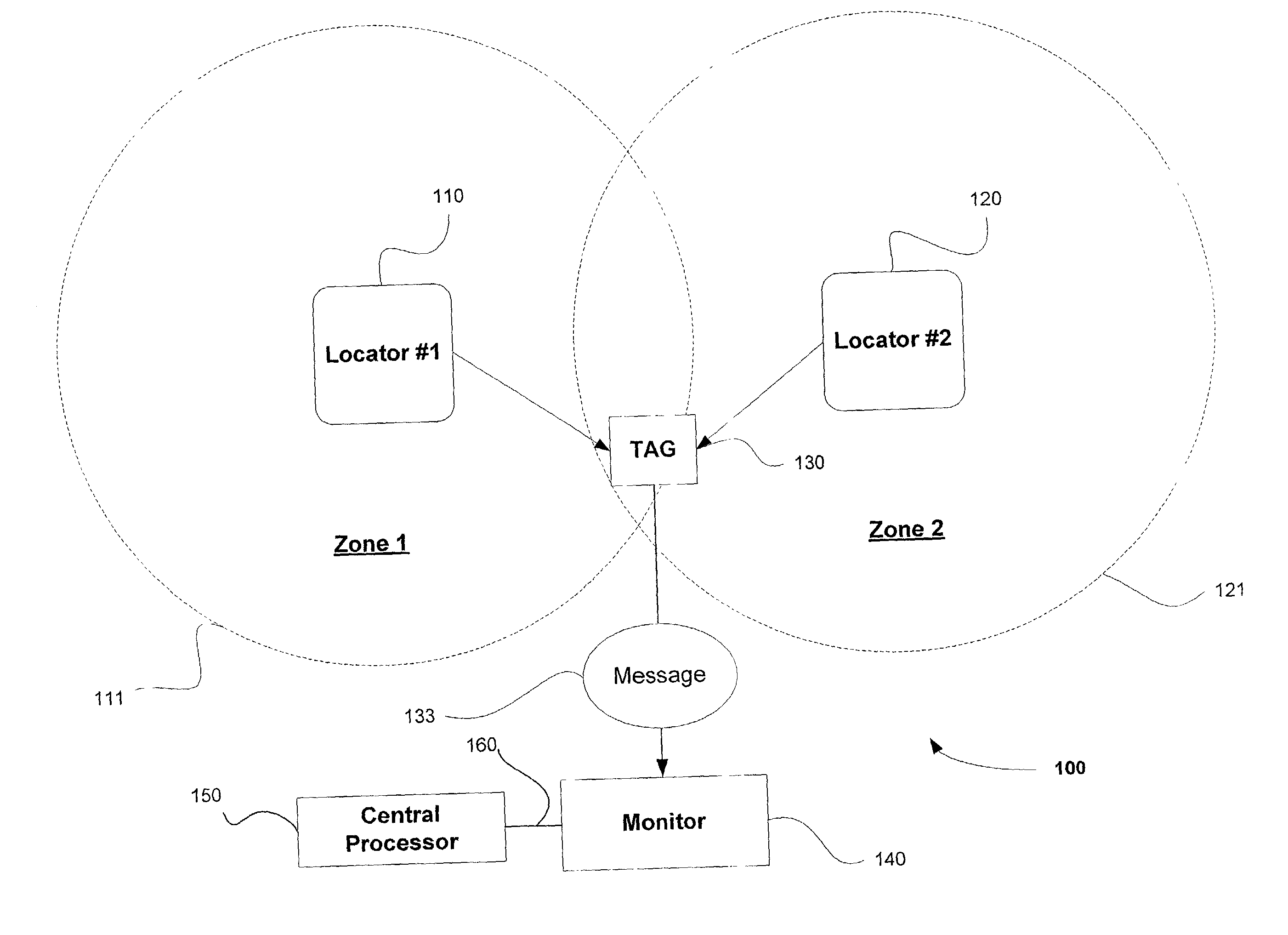
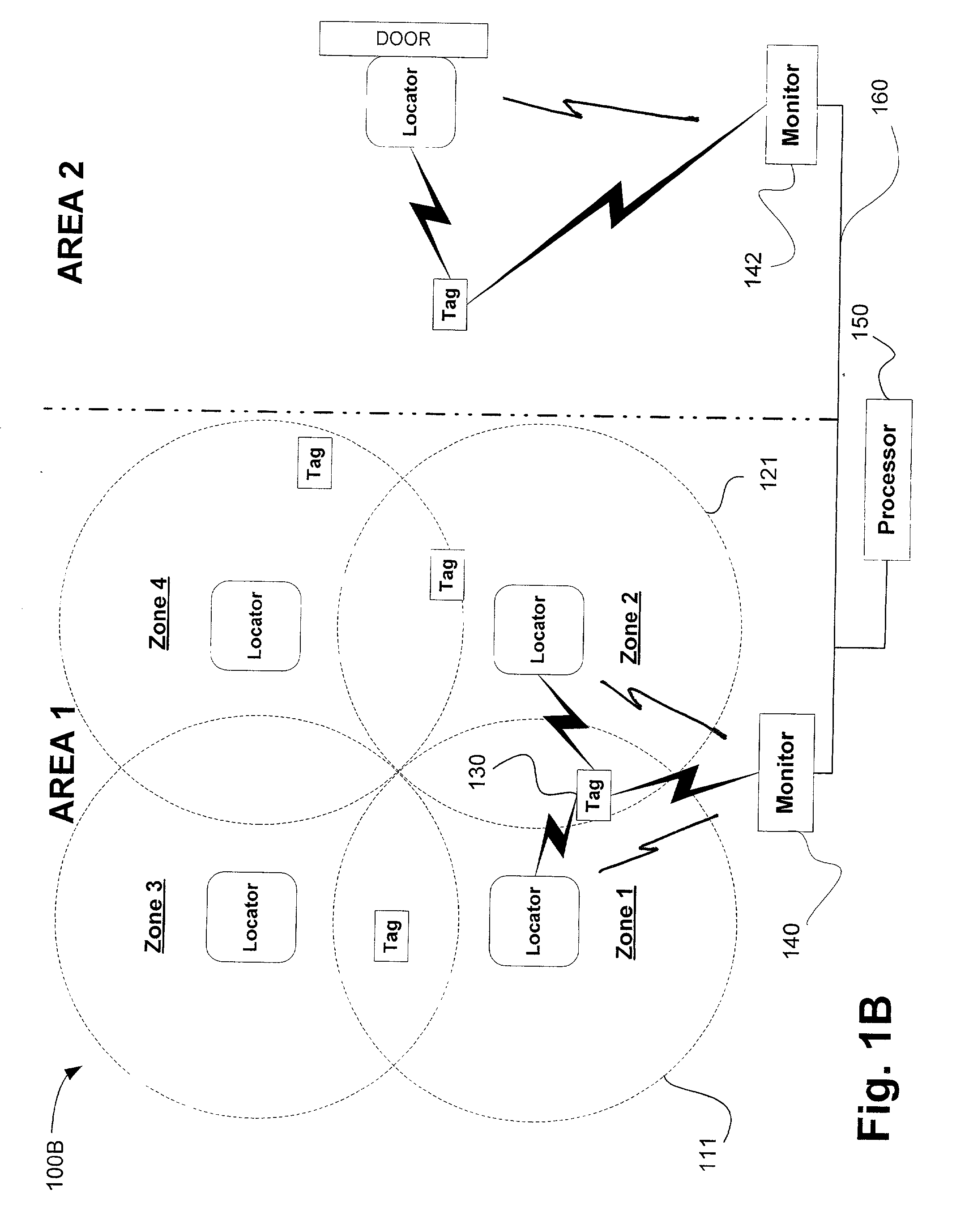
[0026] For example, a system according to various embodiments of the invention includes a transmitter or locator unit to broadcast information within a localized area. This type of transmitter is referred to herein as a "locator" or "locator unit." The following terms are also assigned the following meanings: "area" is defined to mean a physical position or a facility (e.g., a yard, building, floor, suite, bay, or unit of storage space); "locator ID" is an identification of a locator that is broadcasting; "zone" is an area of signal reception that may be defined by a strength and direction of signal broadcast a...


PUM


Abstract

Monitoring systems and protocols are disclosed that are flexible in mode operation and format depending on the environment in which they are used. Such monitoring systems and protocols are able to change their utilization automatically, or by received instruction to do so. A location detection system includes one or more low frequency transmitters, one or more radio frequency monitoring tags and one or more receiving devices. The low frequency transmitter transmits location identification information, such as the transmitter ID, to a tag in the vicinity of the transmission. The tag relays the transmitter ID using a higher frequency transmission sent from the tag to the receiver. Communication protocols are disclosed that enable deciphering of multiple tag transmissions starting simultaneously.

Description

PRIORITY[0001] This application claims benefit under 35 U.S.C. .sctn. 119(e) of copending U.S. patent application Ser. No. 60 / 298322 which was filed on Jun. 14, 2001 and is incorporated herein by this reference.[0002] 1. Field of the Invention[0003] The present invention relates to wireless identification systems and protocols and more specifically to systems used for detection, identification, control and / or location of events and / or objects.[0004] 2. Related Art[0005] Conventional data communication systems have been applied to accomplish object identification using the medium of radio broadcast. Such radio frequency identification (RFID) systems find application in the fields of materials handling, inventory control, and generally in the field of tracking personnel, objects, and animals.[0006] Wireless monitoring systems, such as tag systems, are well known for detecting, locating and / or identifying coded articles. A variety of techniques and systems have been used to determine t...

Claims


Application Information

Patent Timeline
IPC IPC(8): G01S13/74G06K7/00G06K19/07G07C9/00H04B1/59H04B5/02
CPCG06K7/0008G06K7/10079G06K7/10297G07C9/00111G07C9/28
Inventor LASTINGER, ROCRODGERS, JAMESFOWLER, WILLIAMFREIWALD, DEAN
Owner RF CODE
Learn More