Optical disk having multiple write layers, optical disk manufacturing method, optical disk device and optical disk write/read method

a technology of optical disks and write layers, applied in optical recording/reproducing/erasing methods, instruments, mechanical recording, etc., can solve problems such as unstable state of write/read beams reaching the second write film 131, increase read error rate, and unstable size of pits for writing

Inactive Publication Date: 2003-02-13
NEC CORP
View PDF8 Cites 5 Cited by
  • Summary
  • Abstract
  • Description
  • Claims
  • Application Information

AI Technical Summary

Problems solved by technology

A problem with this prior art is that, when the write / read beam is transmitted by the first write film 130 and focuses on the second write film 131 to write or read in the write / read type optical disk having two layers of write films, the state of the write / read beam reaching the second write film 131 becomes unstable.
As a consequence, in writing, the size of the pits for writing is unstable and, in reading, the read error rate rises.

Method used


Image

  • Optical disk having multiple write layers, optical disk manufacturing method, optical disk device and optical disk write/read method
  • Optical disk having multiple write layers, optical disk manufacturing method, optical disk device and optical disk write/read method
  • Optical disk having multiple write layers, optical disk manufacturing method, optical disk device and optical disk write/read method

Examples


first embodiment

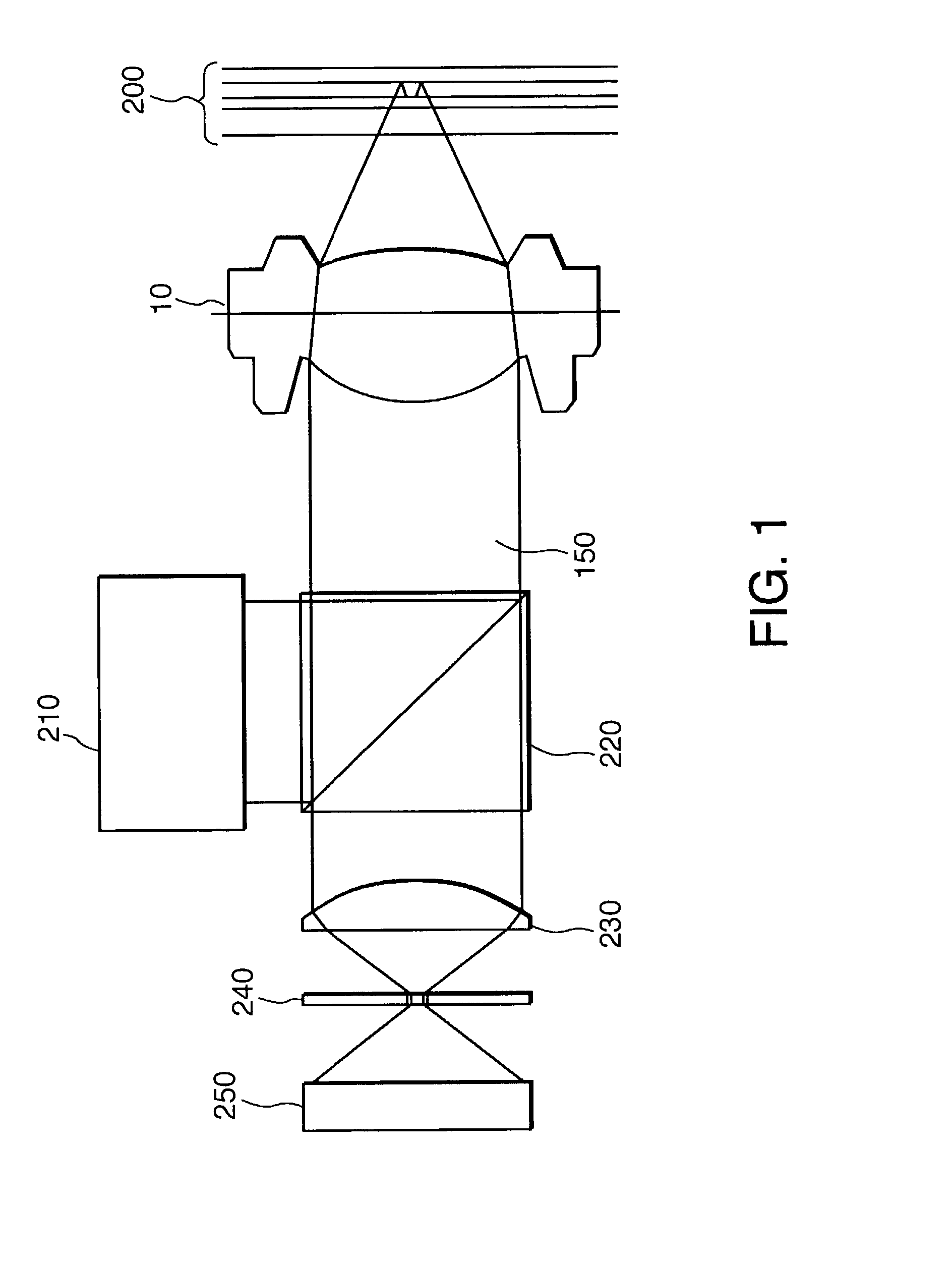
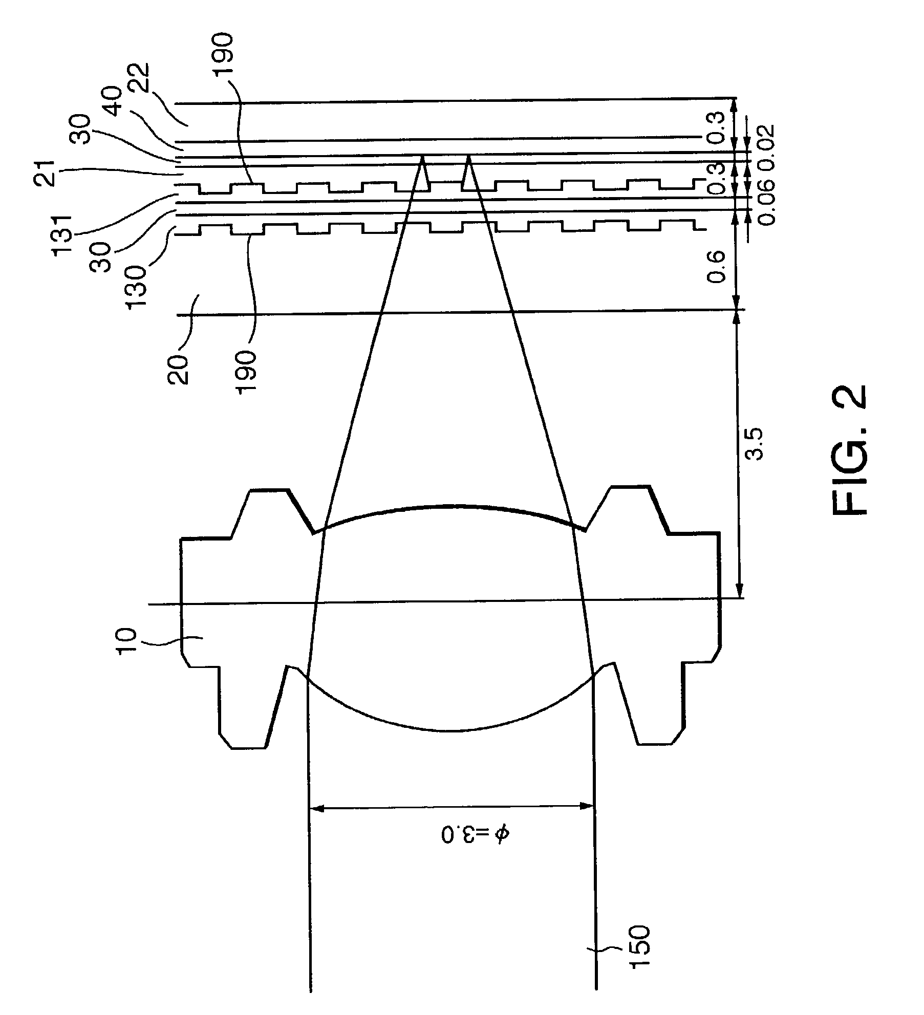
[0046] FIG. 2 is a schematic diagram of the configuration of the objective lens and the optical disk in particular in the overall configuration of the optical disk device and its optical disk in the invention. As the objective lens, the 0.6 t / 1.2 t bifocal objective lens 10 is used. The 0.6 t / 1.2 t bifocal objective lens 10 may be either a double lens type (which meets the bifocal need by switching between two laterally arranged lenses according to the point to be focused on) or a hologram type (which differs between the central part and the peripheral part of the lens in the position where the transmitted light is focused; in this case, where the write / read beam is transmitted by the central part of the lens when it is to serve as a 1.2 t lens or by the peripheral part of the lens when it is to serve as a 0.6 t lens). The 0.6 t / 1.2 t bifocal objective lens 10 is a bifocal objective lens whose tolerance is 0.6.+-.0.03 mm when the lens is used for 0.6 t focusing or 1.2.+-.0.1 mm for ...

second embodiment

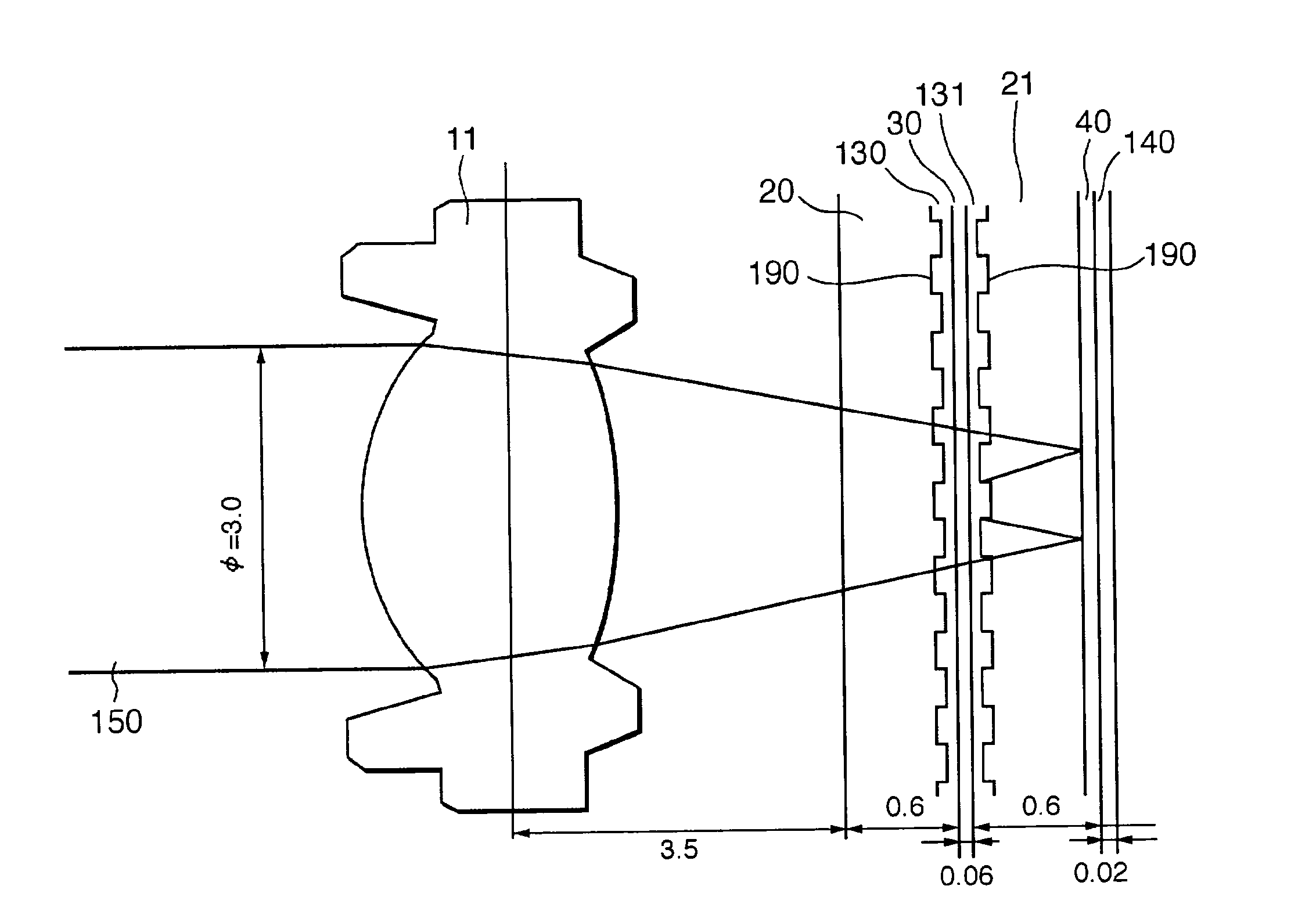
[0072] FIG. 6 is a schematic diagram of the configuration of the objective lens and the optical disk in particular in the overall configuration of the optical disk device and its optical disk in the invention. As the objective lens, the 0.6 t / 1.8 t bifocal objective lens 11 is used. The 0.6 t / 1.8 t bifocal objective lens 11 may be either a double lens type or a hologram type. The optical disk has a structure in which there are stacked, enumerated in the direction of the write / read beam comes incident in the order of its travel, the transparent disk substrate 20 and the translucent write film 130 provided with the grooves 190, having a combined thickness of 0.6 mm; the transparent adhesive layer 300 of 0.06 mm in thickness; the translucent write film 131, the transparent disk substrate 21 provided with the grooves 190 and the aluminum reflective layer 40 of 60% or more in reflection factor, having a combined thickness of 0.6 mm; and a protective film 140 of 0.02 mm in thickness.

[0073...


PUM

PropertyMeasurementUnit
thicknessaaaaaaaaaa
thicknessaaaaaaaaaa
distanceaaaaaaaaaa

Abstract

An optical disk, a method for manufacturing an optical disk, an optical disk device and a method for writing / reading an optical disk, wherein the optical disk is of a write / read type having two layers of write films, enabling the state of the write / read beam to be kept constant when writing onto or reading out of a second write film without being affected by variations in the write state of a first write film, is to be provided. In an optical disk configured by stacking, enumerated in the direction of incidence of a write / read beam, a disk substrate, a first write film, an adhesive layer, a second write film, another disk substrate and an aluminum reflective layer, when performing read / write onto or out of a write film which is the second write film, the write / read beam is focused on the second write film after being transmitted by the disk substrate, the first write film, the adhesive layer, the second write film and the other disk substrate and reflected by the aluminum reflective layer.

Description

[0001] The present invention relates to an optical disk, an optical disk manufacturing method, an optical disk device and an optical disk write / read method, and more particularly to an optical disk having multiple write layers, a manufacturing method therefor, an optical disk device using the disk and a write / read method for the optical disk.DESCRIPTION OF THE RELATED ART[0002] Conventionally, an optical disk of this kind having multiple write layers, a manufacturing method therefor, an optical disk device using the optical disk and a write / read method for the optical disk are used for large-capacity writing.[0003] FIG. 9 is a schematic diagram of the configuration of an objective lens and an optical disk in particular in the overall configuration of an optical disk according to the prior art having multiple write layers and an optical disk device for writing onto and reading out of the disk. The objective lens used here is a 0.6 t objective lens 12 (which means that the lens focuse...

Claims


Application Information

Patent Timeline
Patent Type & Authority Applications(United States)
IPC IPC(8): G11B7/00G11B7/004G11B7/0045G11B7/005G11B7/135G11B7/1353G11B7/24G11B7/26
CPCG11B7/0045G11B7/005G11B7/1353G11B7/24G11B7/26G11B2007/0013
Inventor ISHIZUKA, KENICHI
Owner NEC CORP
Why Eureka
Try Eureka