CD-fixing device

A technology for fixing device and optical disc, applied in the directions of optical record carrier and optical record carrier manufacturing, etc., can solve the problems of inability to stabilize the adsorption and positioning of optical disc, difficult to overcome centrifugal force, easy sliding of optical disc, etc. The effect of convenient and quick positioning

Inactive Publication Date: 2010-07-21
HENAN KAIRUI DIGITAL
View PDF0 Cites 3 Cited by
  • Summary
  • Abstract
  • Description
  • Claims
  • Application Information

AI Technical Summary

Problems solved by technology

[0005] The existing solution only relies on the central vacuum pipe in the drive shaft to vacuum absorb the inner side of the disc. In high-speed rotation, because only the inner ring is adsorbed, it is not easy to overcome the centrifugal force generated during high-speed rotation. The disc is easy to slide and the adsorption force is weak. It is not possible to stably and reliably adsorb and position the optical disc; therefore, there is an urgent need for a device that is strong in adsorption, safe and reliable, easy to manufacture and maintain, and simple in structure and is suitable for fixing the optical disc during the manufacturing process of the optical disc.

Method used


Image

  • CD-fixing device
  • CD-fixing device
  • CD-fixing device

Examples


Embodiment Construction

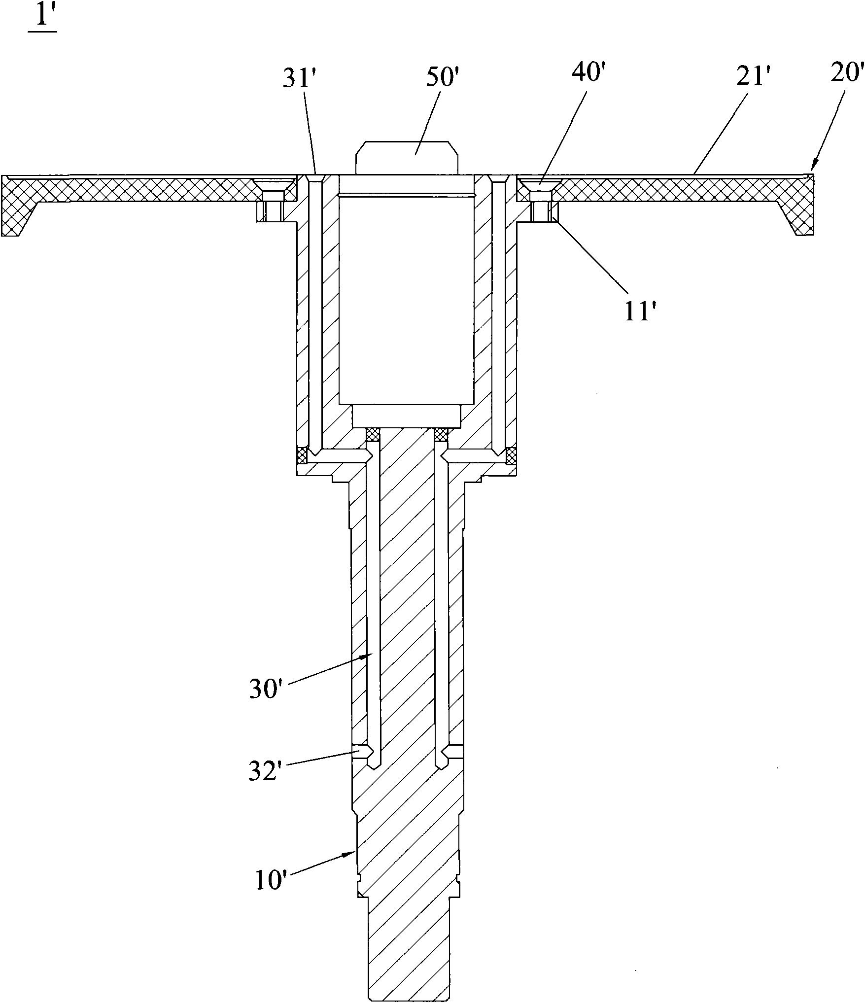
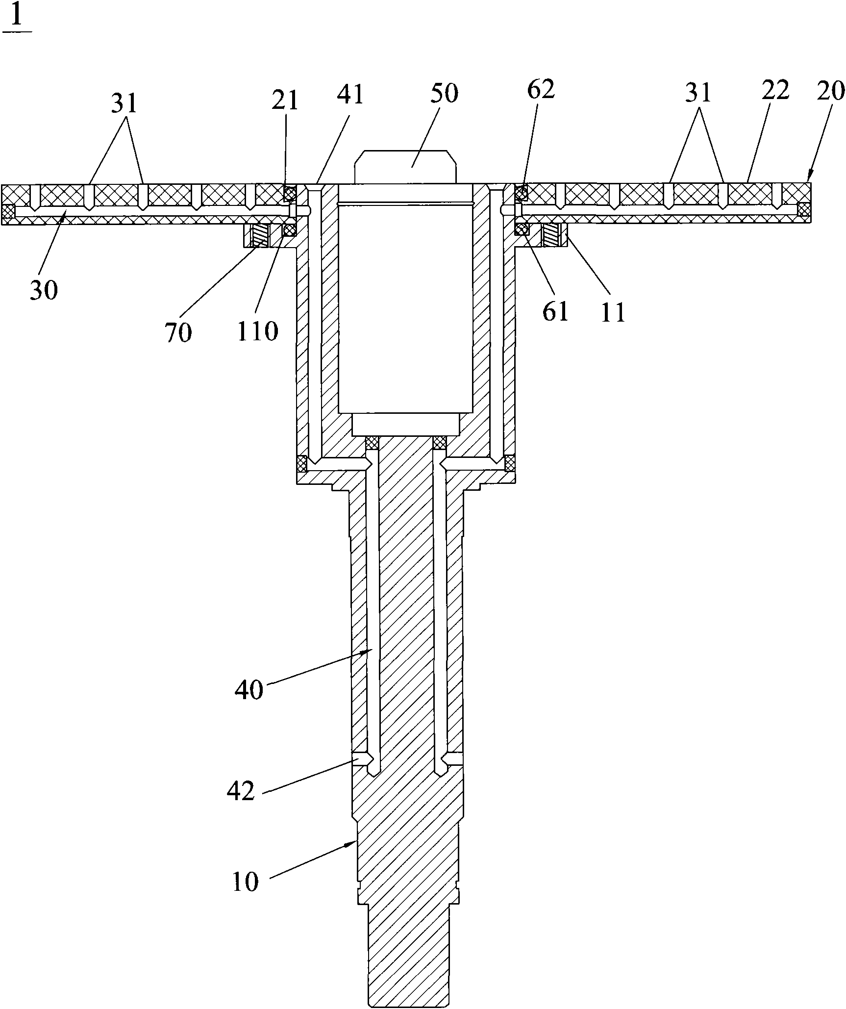
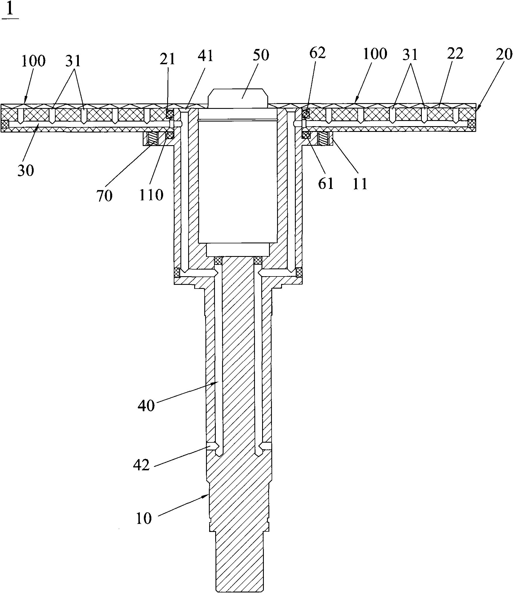
[0016] Such as figure 2 and image 3 As shown, the optical disk fixing device 1 of the present invention includes a turntable 20, a transmission shaft 10 and an adsorption pipeline system. Through the central hole of the turntable 20 and sealed and fixedly connected with the turntable 20, the upper end of the transmission shaft 10 protrudes out a protrusion 50 for the optical disc 100 to pass through, and one end of the adsorption pipeline system runs through the turntable The upper surface 22 of 20 is located on the same plane as the upper surface 22, and the other end of the adsorption pipeline system penetrates the transmission shaft 10 and passes through the transmission shaft 10 and the external vacuum device (not shown in the figure). ), the external drive device drives the transmission shaft 10 to rotate, and the transmission shaft 10 drives the turntable 20 to rotate. The adsorption pipeline system includes a number of side vacuum pipelines 30 and a central vacuum pip...


PUM


Abstract

The invention discloses a compact disk (CD)-fixing device which comprises a turnplate, a rotating shaft and an absorption pipeline system. The lower end of the rotating shaft is connected with an external driving device; the upper end of the rotating shaft penetrates through a central hole of the turnplate and is hermetically and fixedly connected with the turnplate, the absorption pipeline system comprises a plurality of mutually communicated bypass vacuum pipelines and a central vacuum pipeline which penetrates into the rotating shaft, one end of the central vacuum pipeline penetrates through the upper end of the rotating shaft to form central suckers which are evenly distributed in equal diameters by using the rotating shaft as a center, and the other end of the central vacuum pipeline penetrates through the rotating shaft to form a central interface and is communicated with an external vacuumizing device. The bypass vacuum pipelines penetrate into the turnplate, one end of each bypass vacuum pipeline is communicated with the central vacuum pipeline, the other end of each bypass vacuum pipeline penetrates through the upper surface of the turnplate to form side suckers which are evenly distributed at stages by using the rotating shaft as a center, and the side suckers and the central suckers are arranged on the same plane. The invention aims to provide the CD-fixing device which has strong adsorption force, safety, reliability, convenient manufacture and maintenance and simple structure and is suitable for fixing a CD in the CD manufacture process.

Description

technical field [0001] The invention relates to a positioning of an optical disc, in particular to an optical disc fixing device capable of fixing the optical disc in high-speed rotation. Background technique [0002] With the continuous development of the economy and the current environment, more and more optical discs are used. However, the production process of optical discs is quite complicated, especially after several processes. Therefore, during the production process, optical discs must be moved repeatedly. Perform multiple processing; at the same time, when the disc is moving, it must be placed on a fixed processing position accurately and stably, so as to improve the processing efficiency. [0003] Please refer to Fig. 1, the existing disc fixing device 1 ', which comprises a turntable 20 ', a transmission shaft 10 ', a central vacuum pipeline 30 ', a set screw 40 ', an external driving device and a vacuum device, and the transmission shaft 10 ' The lower end is c...

Claims


Application Information

Patent Timeline
Patent Type & Authority Applications(China)
IPC IPC(8): G11B7/26
Inventor 杨明生范继良谢威武王勇
Owner HENAN KAIRUI DIGITAL
Why Eureka
Try Eureka