Original disk fabrication method, magnetic recording medium manufacturing method and magnetic recording medium

a manufacturing method and magnetic recording medium technology, applied in photomechanical devices, nanoinformatics, instruments, etc., can solve the problems of difficult control of the atmosphere, difficult positioning and complicated processes, and large demerit in mass production, and achieve favorable address deciphering and high recording density

Inactive Publication Date: 2010-10-19
KK TOSHIBA
View PDF11 Cites 2 Cited by
  • Summary
  • Abstract
  • Description
  • Claims
  • Application Information

AI Technical Summary

Benefits of technology

[0015]An object of the present invention is to provide a fabrication method of an original disk on which the recording density is high and favorable address deciphering is possible when fabricating a pattern of a patterned medium on which a data track area is divided by non-magnetic parts, by using an electron beam irradiating apparatus, and provide such a magnetic recording medium and its manufacturing method.

Problems solved by technology

Especially in the case of a wide area, however, it is considered to be difficult to control the atmosphere so as to arrange dots in good order As to this problem, it is proposed to use a guide as described in Japanese Patent No. 3793040.
Otherwise, one of the regions is added later resulting in difficult positioning and complicated processes.
In general, however, the beam current value in the exposure spot cannot help being made as small as several to several hundreds pA, resulting in great demerit in mass production.
If on the contrary the bit length is shortened to increase the recording density in the address part as well, deciphering is affected, resulting in operation troubles of the hard disk.

Method used


Image

  • Original disk fabrication method, magnetic recording medium manufacturing method and magnetic recording medium
  • Original disk fabrication method, magnetic recording medium manufacturing method and magnetic recording medium
  • Original disk fabrication method, magnetic recording medium manufacturing method and magnetic recording medium

Examples


first embodiment

[0031]A fabrication method of an original disk according to a first embodiment of the present invention will now be described with reference to FIGS. 1(a) to 7.

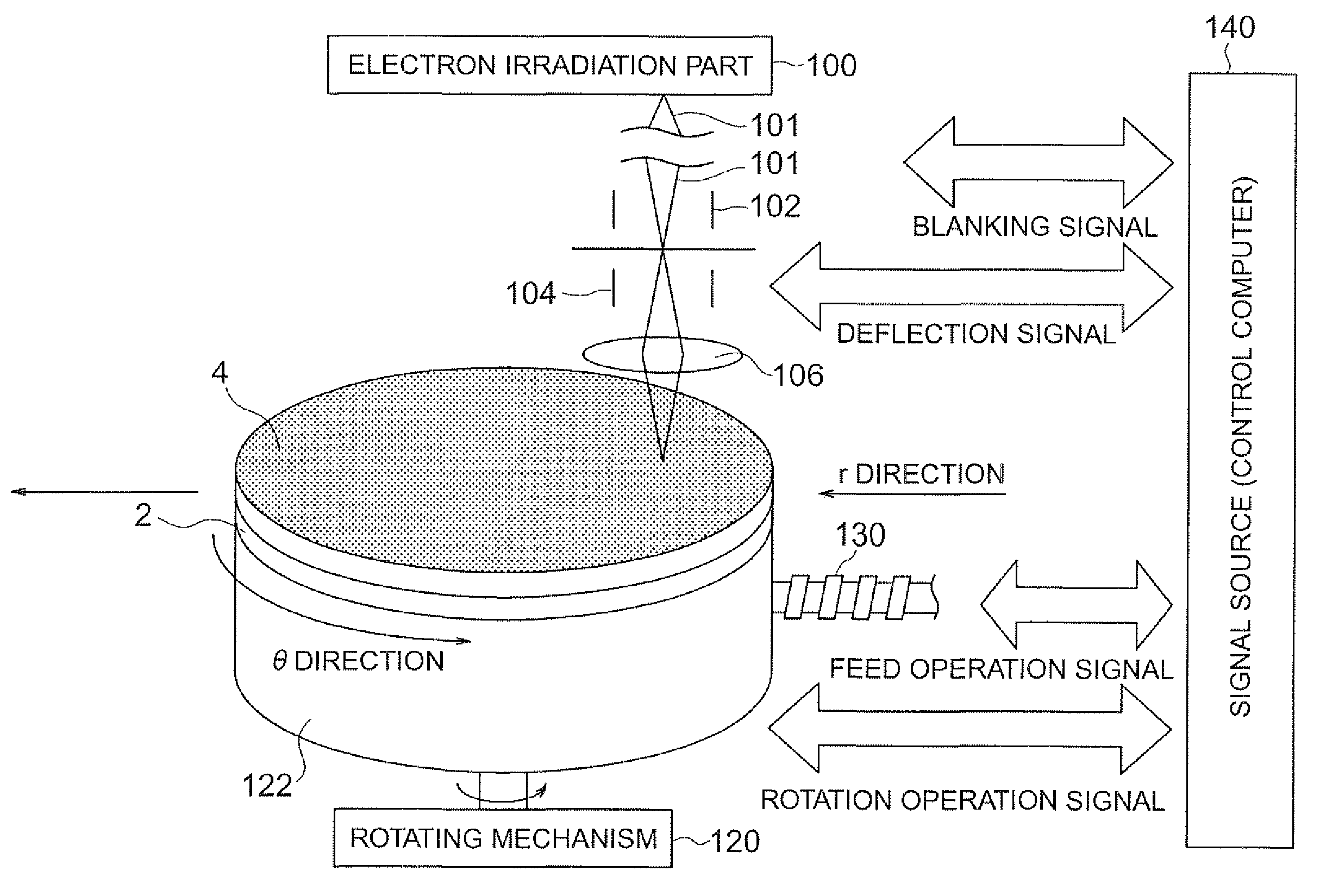
[0032]FIG. 7 is a diagram showing a schematic configuration of an electron beam irradiating apparatus used in the fabrication method of the original disk according to the present embodiment. This electron beam irradiating apparatus includes a rotating mechanism 120 to rotate a stage 122 on which a substrate 2 having a photosensitive resin film 4 formed thereon is placed, a moving mechanism 130 to move the stage 122 in one horizontal direction, and an electron beam irradiation part 100 to irradiate the photosensitive resin film 4 with an electron beam 101. The place through which the electron beam 101 passes is kept in the vacuum state. The electron beam 101 emitted from the electron beam irradiation part 100 passes through a lens system including a condenser lens and an object lens 106 and arrives at the photosensitive resin ...

third example

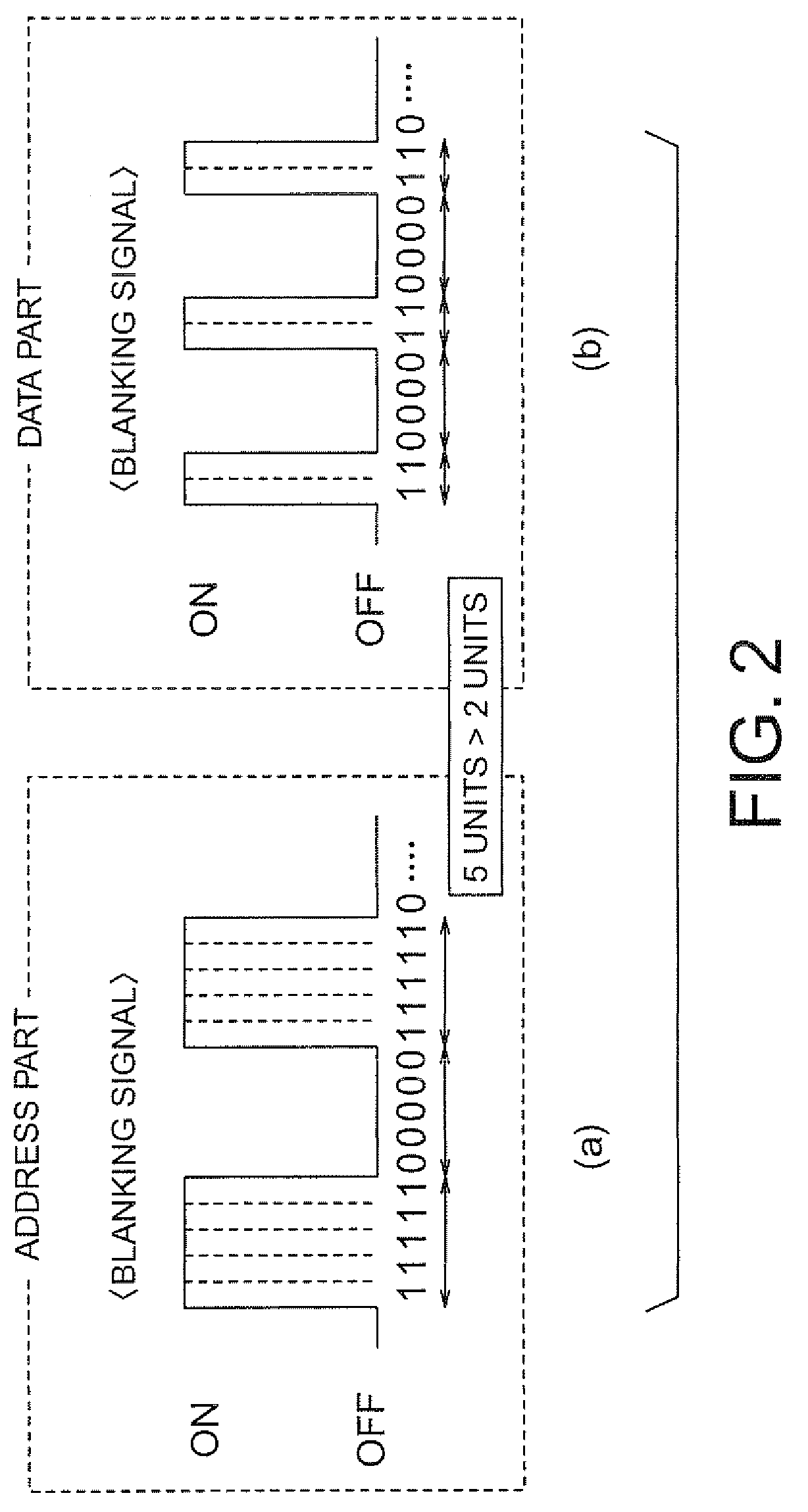
[0037]A third example is obtained by making one signal output unit of ON and OFF of the blanking signal in the address part in the second example equal to a plurality of times as long as one signal output unit of the blanking signal in the data part as shown in FIGS. 3(a) and 3(b). For example, one signal output unit of the blanking signal in the data part is made equal to one unit as shown in FIG. 3(b), whereas one signal output unit of the blanking signal in the address part is made equal to four units as shown in FIG. 3(a). At this time, the electron beam used to irradiate the region corresponding to the address part may be an electron beam corresponding to each of the four blanking signals, or may be overlapping electron beams corresponding to the four blanking signals as a whole as described with reference to the first example.

[0038]When drawing a pattern by irradiating the photosensitive resin film 4 with an electron beam, an original disk is fabricated by changing the width o...

second embodiment

[0050]A magnetic recording medium according to a second embodiment of the present invention will now be described with reference to FIGS. 8A to 9F. The magnetic recording medium according to the present embodiment is a magnetic bit-patterned recording medium of magnetic substance-patterned type. When manufacturing it, the electron beam lithography method described with reference to the first embodiment is used in the exposure process. Hereafter, the manufacturing process of the magnetic recording medium according to the present embodiment will be described.

[0051]Photosensitive resin (hereafter referred to as resist) 4 is applied onto a substrate 2 (see FIG. 8A). The resist 4 is exposed to an electron beam as shown in FIG. 8B.

[0052]Thereafter, the resist 4 is developed by using a developing solution to form a resist pattern 4a (FIG. 8B shows the case where a positive type resist is used). A resist original disk is fabricated (see FIG. 5C). A post-bake process may be executed before d...


PUM

PropertyMeasurementUnit
sizeaaaaaaaaaa
sizeaaaaaaaaaa
sizeaaaaaaaaaa

Abstract

It is made possible to fabricate a bit-patterned magnetic recording medium having a high recording density and making favorable address deciphering possible. An original disk fabrication method for irradiating a photosensitive resin film with an electron beam to draw a pattern, the method includes: irradiating the electron beam by using a plurality of blanking signals every rotation of a stage per bit unit, when drawing the pattern in a part corresponding to an address part on a photosensitive resin film.

Description

CROSS-REFERENCE TO RELATED APPLICATION[0001]This application is based upon and claims the benefit of priority from prior Japanese Patent Application No. 2007-38336 filed on Feb. 19, 2007 in Japan, the entire contents of which are incorporated herein by reference.BACKGROUND OF THE INVENTION[0002]1. Field of the Invention[0003]The present invention relates to an original disk fabrication method, a magnetic recording medium manufacturing method and a magnetic recording medium.[0004]2. Related Art[0005]In the technical trend toward the higher density of the magnetic disk (hereafter referred to as hard disk as well), a medium structure on which a magnetic part region issuing a magnetic signal is divided by nonmagnetic parts, i.e., the so-called medium structure of discrete type as described in JP-A 2004-110896 (KOKAI) is proposed. In additions a patterned medium on which a data track part is not only divided by grooves in the circumferential direction but also divided every data bit as d...

Claims


Application Information

Patent Timeline
Patent Type & Authority Patents(United States)
IPC IPC(8): G11B5/82
CPCB82Y10/00B82Y40/00G11B5/743G11B5/82G11B5/855G11B5/865H01J37/3174G11B9/10
Inventor OKINO, TAKESHI
Owner KK TOSHIBA
Why Eureka
Try Eureka