The above-described heat fixing apparatus, however, suffers from problems as mentioned below.
Also, it is necessary to heat the fixing roller 40 to a predetermined temperature by the electrical energization of the heater 41 during standby and therefore, energy was wastefully used.
Also, even when an attempt is made to cope with the problem by making the thickness of the mandrel 42 small, if an attempt is made to heat the fixing roller by the radiant of the heater 41 as in the above-described example of the related art, heat efficiency is not good and therefore, preliminary heating likewise becomes necessary when the recording material conveying speed becomes high by the higher speed of the image forming apparatus.
Also, when attempt is made to make the temperature rising speed higher by making the thickness of the mandrel 42 smaller, the strength of the mandrel 42 is not sufficient and therefore, when the mandrel is pressurized with a strong pressure force, it is greatly flexed and comes to have cracks or the like therein, and this has led to a problem in durability.
However, the fixing film 63 is formed by a resin layer insufficient in heat
conductivity, and has been unsuitable for the higher speed of the image forming apparatus.
That is, when the image forming apparatus is made higher in speed, the heating speed given to the recording material P from the heater 61 through the fixing film 63 must be increased correspondingly to the higher speed of the apparatus, but for the fixing film 63 made of resin, there is a limitation even if there is taken a measure such as mixing a heat-conductive filler with the film, and it will become impossible to cope with still a higher speed.
However, there arise the new problems of the reduced durability and the rise of driving torque by the friction between the heater and the rotary member.
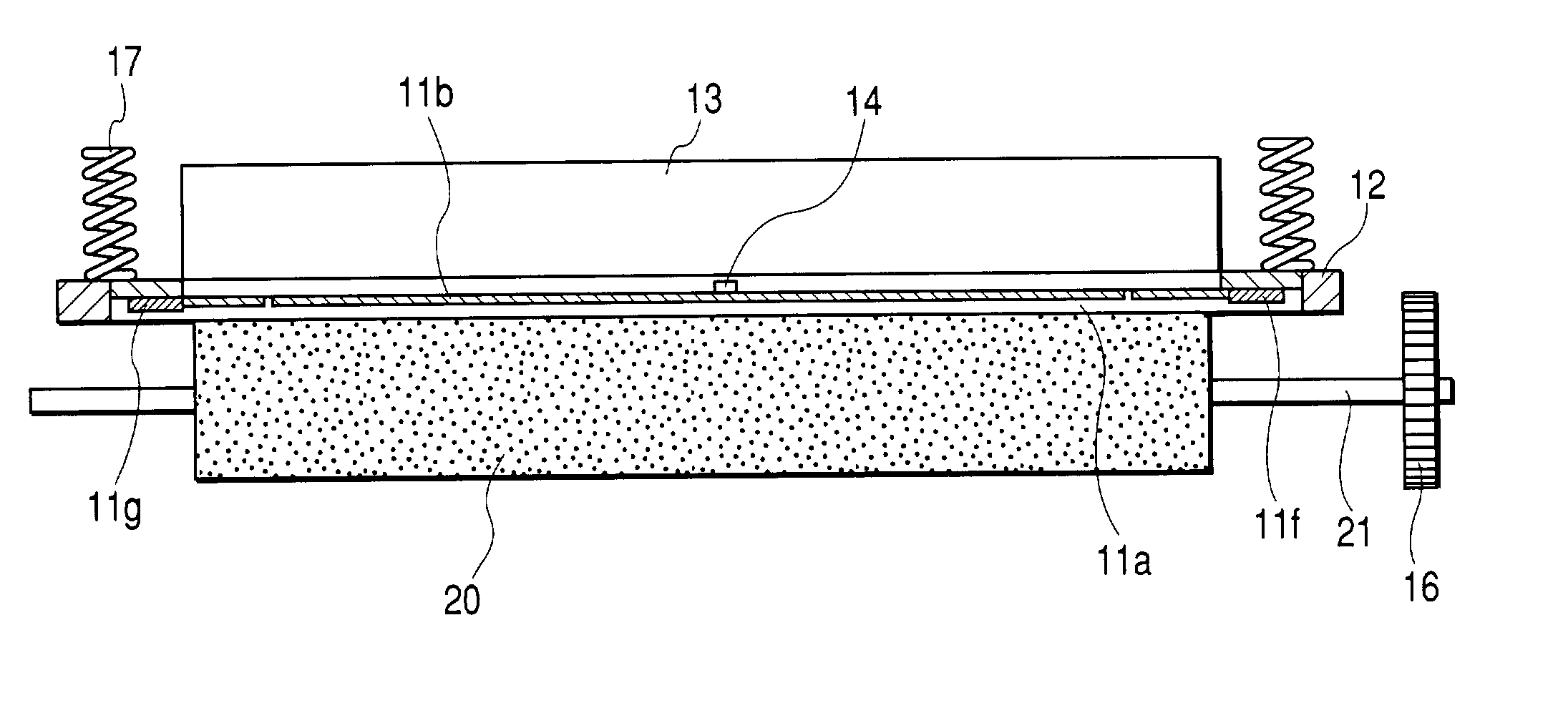
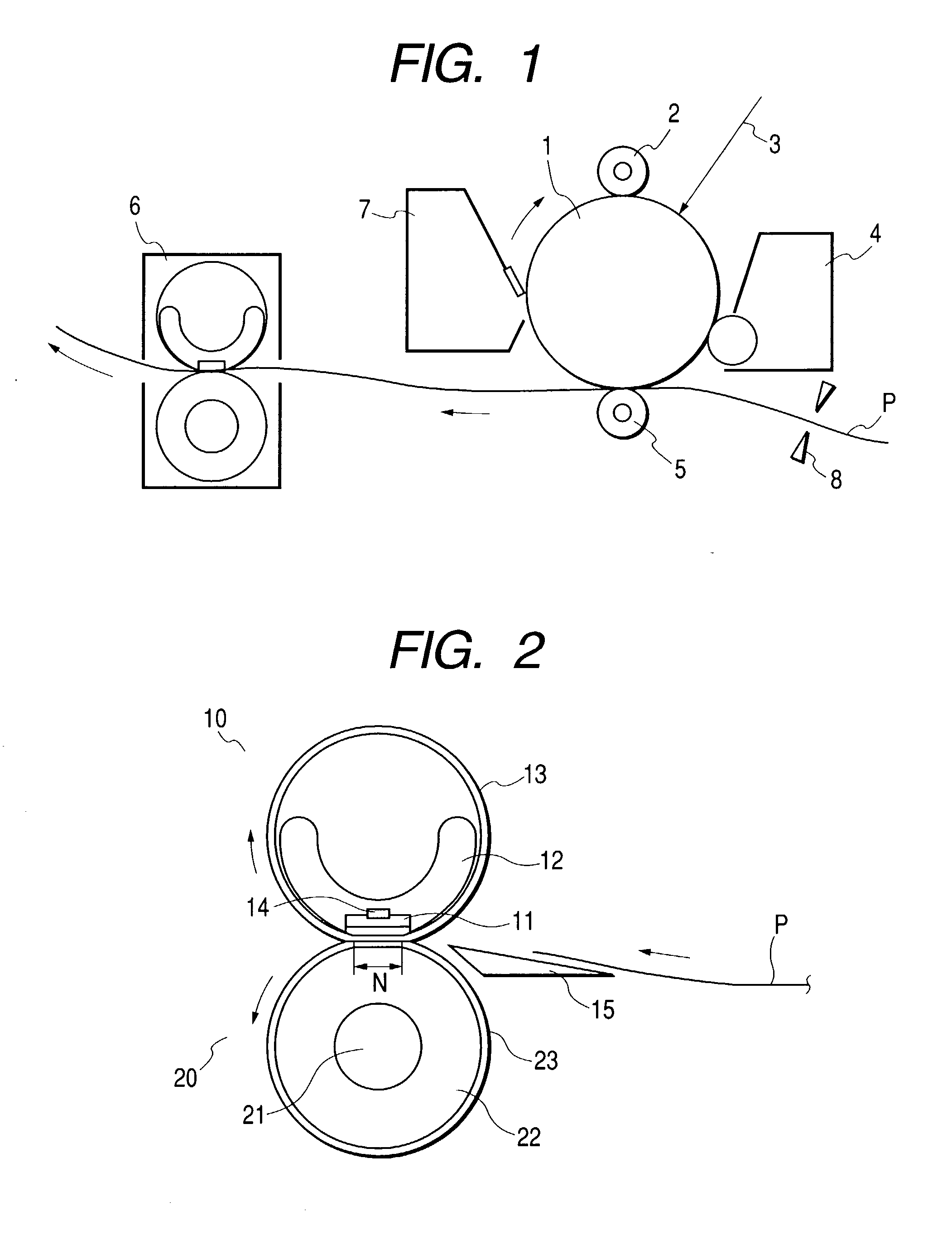
Consequently, if the mold releasable layer is formed too thickly, the aggravation of heat conduction will result and when the metallic sleeve is used in a printer of high treating capability, sufficient
heat supply will become impossible to the toner image on the recording material P in the fixing nip portion N. Consequently, it is necessary to form a thin mold releasable layer on the metallic sleeve 13.
Consequently, if the
surface roughness of the blank tube of the metallic sleeve 13 is great, it will become great
surface roughness even after the application and formation of the mold releasable layer, and the
close contact force with respect to the recording material P will not be obtained in the fixing nip portion N, and the possibility of causing poor fixing will become great.
Consequently, for the higher speed of the image forming apparatus as well, the recording material can be sufficiently heated even within a short conveying time in the fixing nip, and such a problem as poor fixing will not result.
Also, in the evaluation of durability, by using the metallic sleeve of high rigidity, it becomes difficult for the tear from the end portions to occur to the film made of resin, and high enduring performance in obtained.
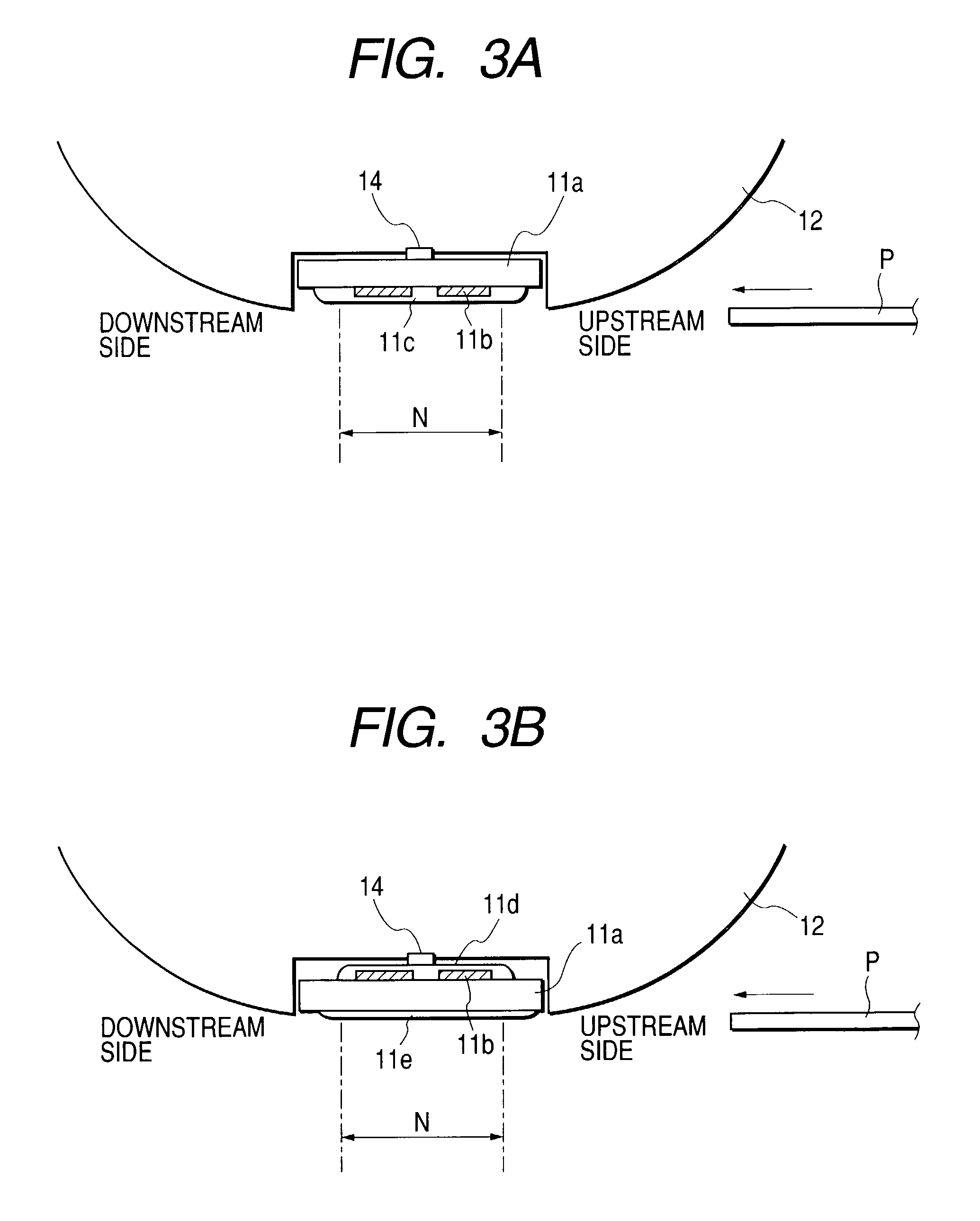
From the result shown above, it will be seen that the surface roughness of the outer surface of the metallic sleeve 13 somewhat affects the temperature in the fixing nip portion N, but when the toner image on the recording material P is heated and fixed, the greater becomes the roughness of the outer surface of the metallic sleeve 13 in the applied state of the mold releasable layer, the more occurs the bad contact with the recording material P, and this leads to poor fixing.
Also, if the thickness of the mold releasable layer exceeds 20 .mu.m, the fixing nip portion N will be come incapable of being sufficiently heated due to the aggravation of heat conduction, and the heat fixing apparatus will become inferior in fixing performance.

