Antireflective coating and method of manufacturing same

Inactive Publication Date: 2002-03-19
FRAUNHOFER GESELLSCHAFT ZUR FOERDERUNG DER ANGEWANDTEN FORSCHUNG EV
View PDF9 Cites 153 Cited by
  • Summary
  • Abstract
  • Description
  • Claims
  • Application Information

AI Technical Summary

Problems solved by technology

As a result of the reflection phenomena occurring on the interface of the transparent media the transparency characteristics as well as the reading suitability of screens or displays are substantially impaired.
The disadvantage of this kind of antireflection treatment resides, however, in the aspect that the hemispheric reflection, i.e. the sum of reflecting and diffuse reflection into the total rear space region is not increased in the most expedient case, so that the background brightness of screen glass surfaces so prepared is comparatively high.
The structure of the interference layer is so configured that destructive interference phenomena occur in the reflected radiation field in suitable wavelength ranges, so that reflexes from light sources are strongly reduced in terms of their brightness.
Even with a visual residual re

Method used


Image

  • Antireflective coating and method of manufacturing same
  • Antireflective coating and method of manufacturing same
  • Antireflective coating and method of manufacturing same

Examples


Embodiment Construction

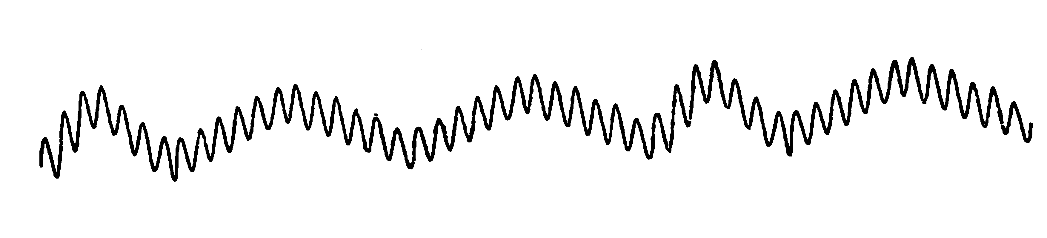
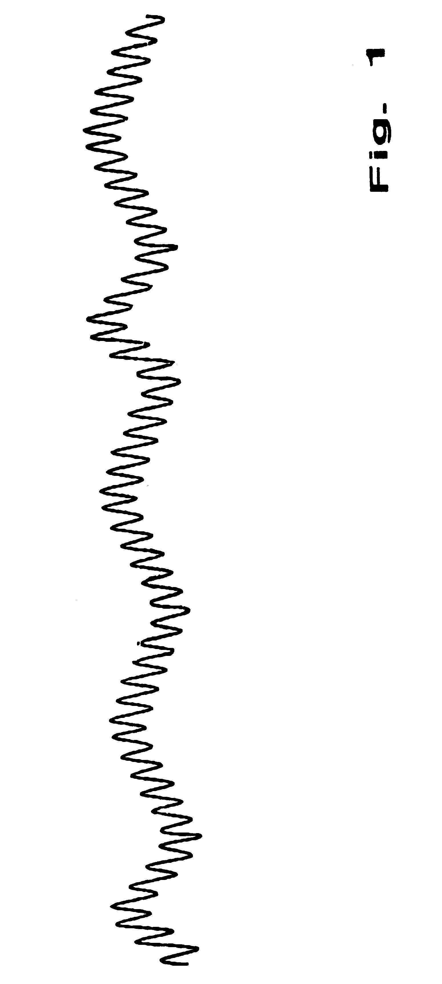
The merely schematic illustration in FIG. 1 shows a surface profile in a cross-sectional view of the inventive antireflective layer. The macro structure is subjected to a stochastic--i.e. non-homogeneous--distribution and, in analogy with the technique of transmission of electromagnetic waves, it corresponds to the form of a carrier wave on which the surface structure illustrated in FIG. 1 may be superimposed. The micro structure is quasi modulated onto the carrier wave or the macro structure, respectively.

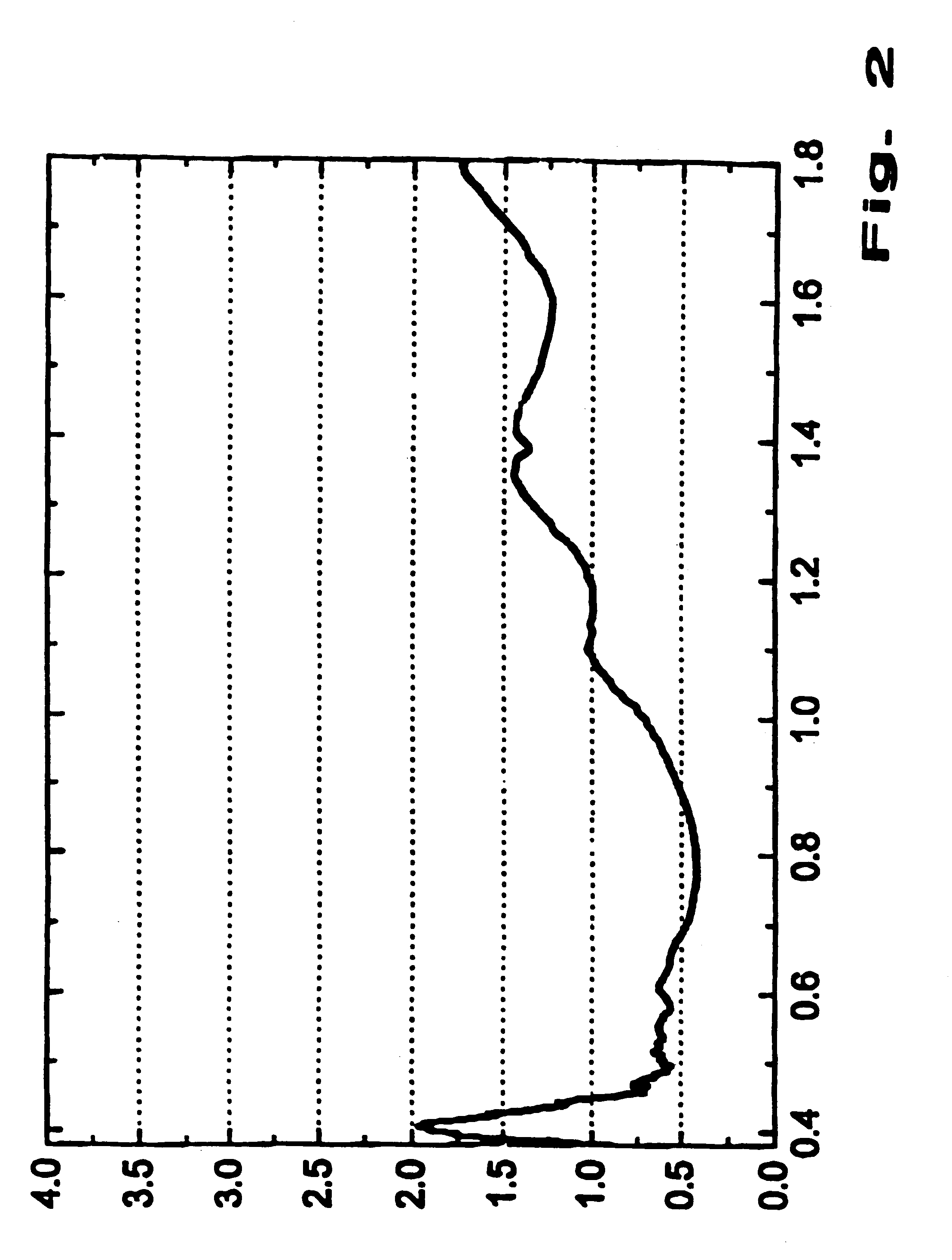
FIG. 2 shows a diagram which corresponds to a measurement for measuring the reflective properties of an optically transparent medium having a refractive index of 1.6. What can be clearly recognised is the fact that the hemispheric reflection is definitely lower than 2% over the entire range of wavelengths in the visible range as well as in the joining infrared range. Comparative measurements with mere antiglare antireflective layers have gone to show that these are higher than the...


PUM

PropertyMeasurementUnit
Lengthaaaaaaaaaa
Depthaaaaaaaaaa
Structureaaaaaaaaaa

Abstract

What is described here is an antireflective coating comprising a carrier layer consisting of an optically transparent material, which, at least on one surface side, presents antireflective properties with respect the wavelengths of the radiation incident on the surface. Moreover, methods of producing the coating are described.The invention excels itself by the provision that the antireflective surface side presents a surface roughness with stochastically distributed structures-the so-called macro structures-and that the macro structures are additionally modulated with surface structures presenting a periodic sequence-the so-called micro structures-which present period or cycle lengths smaller than the wave lengths of the radiation incident on the antireflective surface.

Description

The invention relates to an antireflective coating comprising a carrier layer consisting of an optically transparent material, which presents, at least on one surface side, antireflective characteristics in view of the wavelengths of radiation incident on the surface. Moreover, inventive methods of manufacturing the antireflective coating are disclosed.PRIOR ARTAt the interfaces of transparent media such as glass or synthetic panes, which are preferably used for windows, screens or instrument display surfaces, one part of the light incident on the interfaces is always reflected, i.e. reflected back into the space. As a result of the reflection phenomena occurring on the interface of the transparent media the transparency characteristics as well as the reading suitability of screens or displays are substantially impaired. For an improvement of the transparency properties or the reading suitability of screens of any kind in general antireflection measures are known which take each a d...

Claims


Application Information

Patent Timeline
IPC IPC(8): G02B1/11G02B1/10G02B1/118G02B1/12
CPCG02B1/118Y10T428/24479Y10T428/315
Inventor GOMBERT, ANDREASLERCHENMULLER, HANSJORG
Owner FRAUNHOFER GESELLSCHAFT ZUR FOERDERUNG DER ANGEWANDTEN FORSCHUNG EV
Why Eureka
Try Eureka