Perpetual calendar wall display device having rotatable calendar days

Inactive Publication Date: 2003-03-20
CHIRAFESI JR CHARLES
View PDF0 Cites 38 Cited by
  • Summary
  • Abstract
  • Description
  • Claims
  • Application Information

AI Technical Summary

Problems solved by technology

None of the aforementioned prior art patents disclose or teach the features, configuration and structure of the perpetual cal

Method used


Image

  • Perpetual calendar wall display device having rotatable calendar days
  • Perpetual calendar wall display device having rotatable calendar days
  • Perpetual calendar wall display device having rotatable calendar days

Examples


embodiment 200

Alternate Embodiment 200

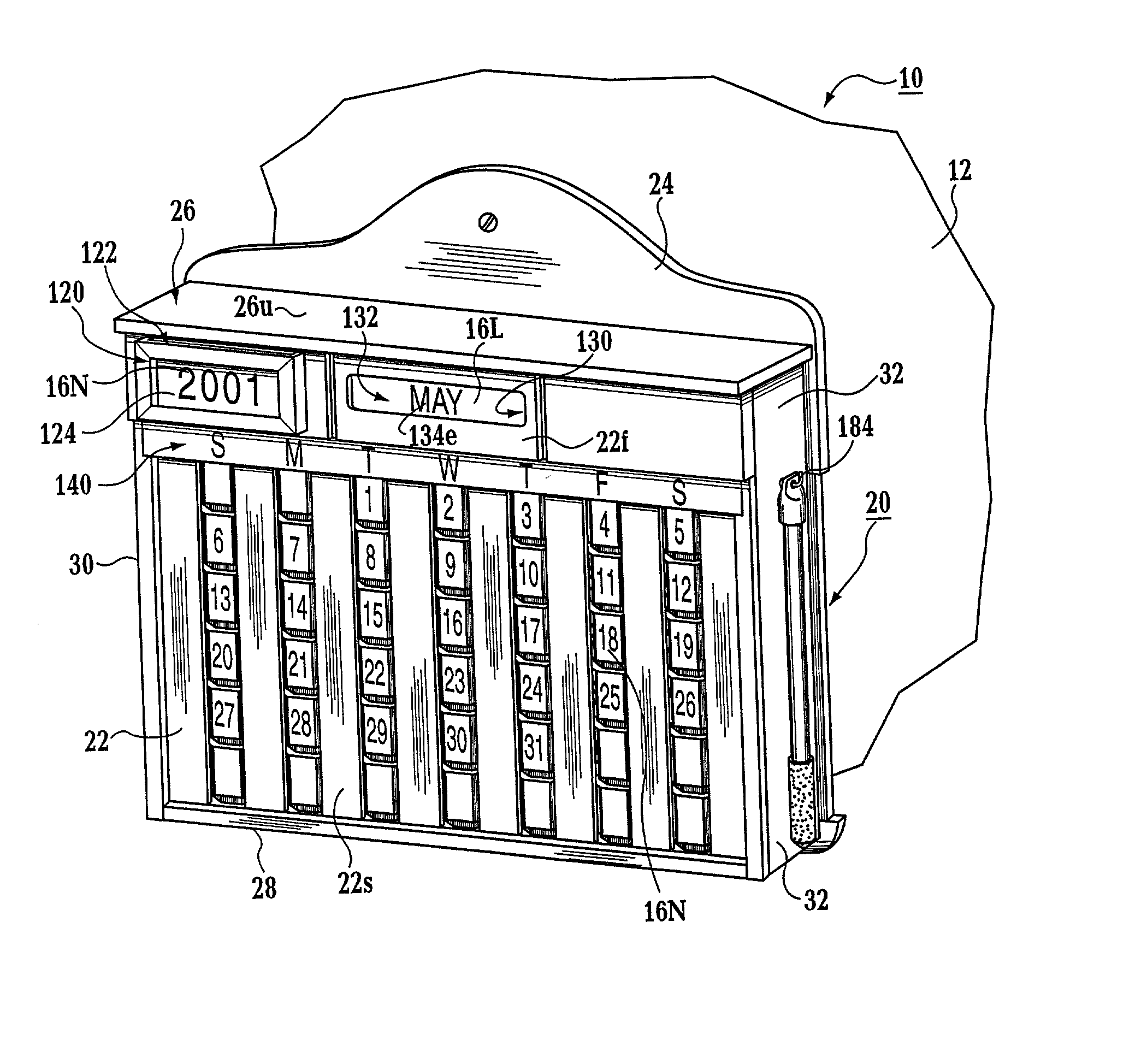
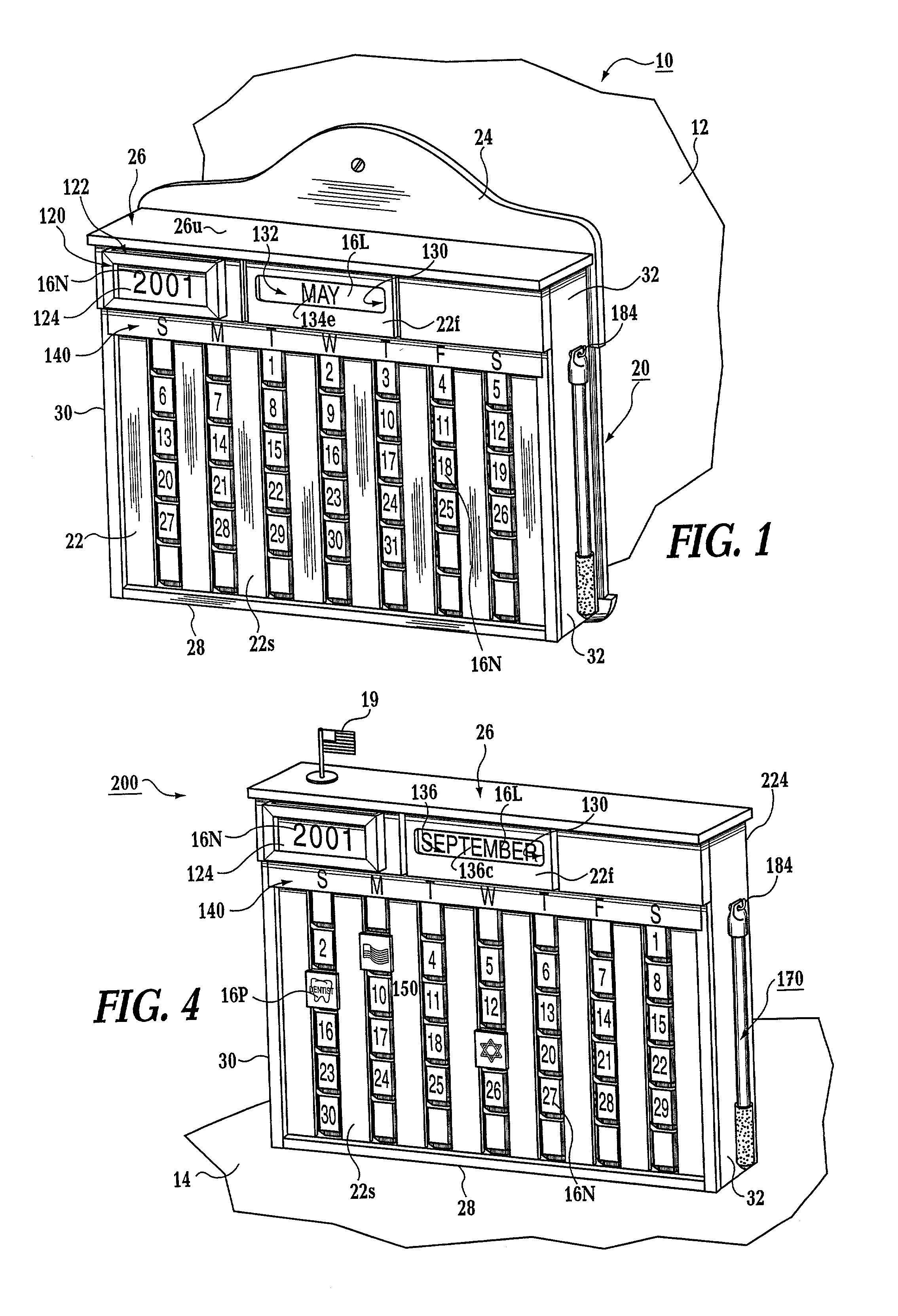
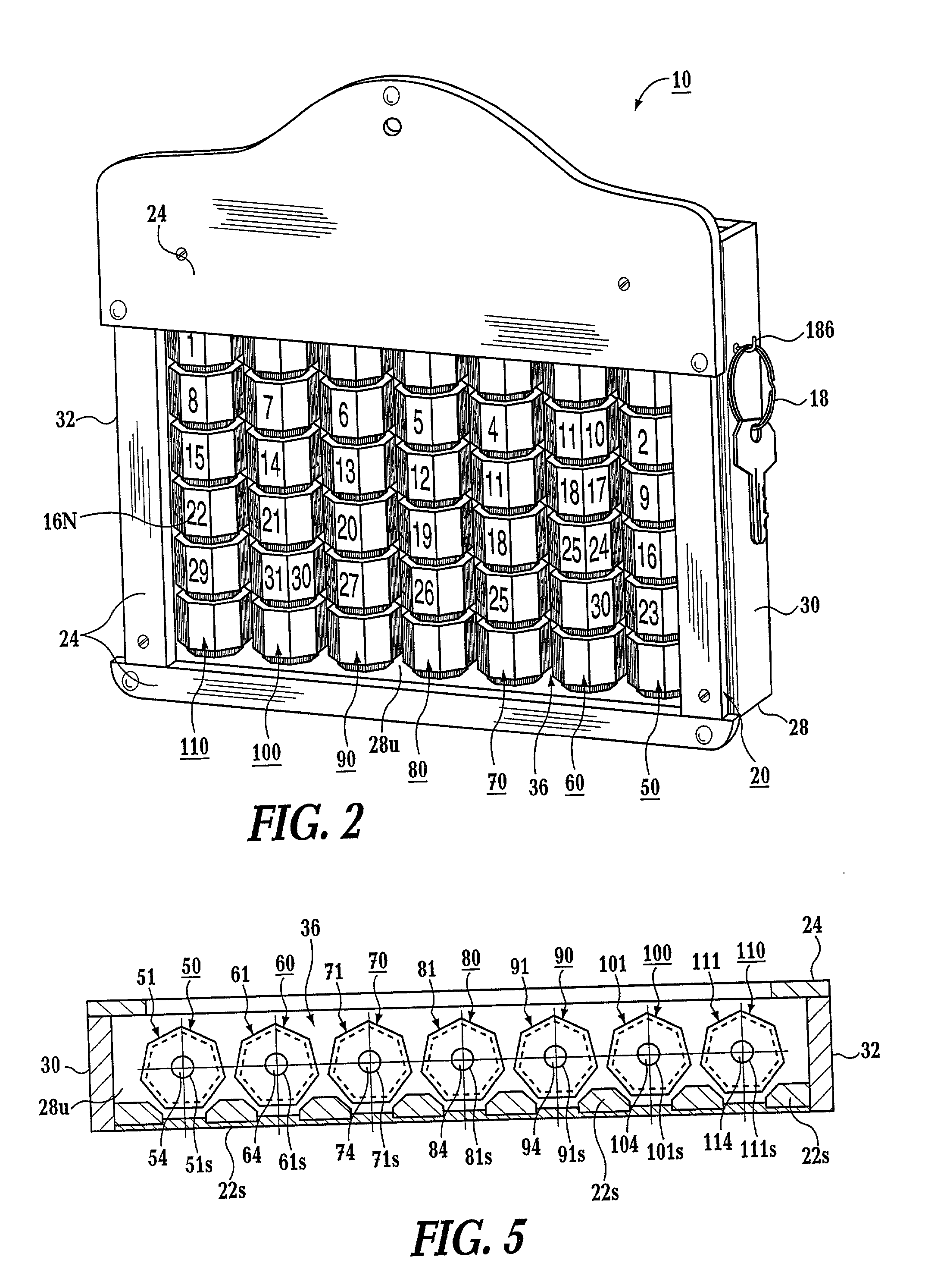
[0049] The perpetual calendar display device 200 and its component parts of the alternate embodiment of the present invention are represented in detail by FIG. 4 of the patent drawings. Perpetual calendar display device 200 is used for counter tops 14, table tops, desks and the like. All aspects of this alternate embodiment of the perpetual calendar display device 200 are exactly the same as the preferred embodiment of the perpetual calendar display device 10 except for the shape and configuration of rear wall 224 being different than rear wall 24, as shown in FIGS. 3A and 4 of the drawings.


PUM


Abstract

A perpetual calendar display device for displaying the calendar date. The perpetual calendar display device includes a calendar housing having a front wall, a rear wall, a top wall, a bottom wall and side walls for forming a first interior compartment. The front wall includes eight (8) elongated vertical spaced-apart strips each having side edges for forming seven (7) elongated vertical spaced-apart display openings. The first interior compartment having mounted therein seven spaced-apart rotatable columns. Each of the rotatable columns includes six (6) vertically spaced-apart display areas, and each of the display areas having up to seven (7) display positions forming a total of at least thirty-seven (37) display positions. Each of the thirty-seven (37) display positions having a number thereon corresponding to the date of a selected month; and the of the thirty-seven (37) display positions being movable into or out of display openings for displaying all of the dates for the selected month. Each of the display windows are for receiving one of the display positions for displaying one of the dates of the selected month.

Description

[0001] The present invention relates to a perpetual calendar display device for displaying all of the dates for each week of a selected month of a given calendar year. More particularly, the perpetual calendar display device includes rotatable vertical columns such that when the user sets the first seven days within the calendar week, the next three weeks fall automatically into place. The user then turns the appropriate other remaining rotatable vertical columns for setting the last few days of a selected month.[0002] Perpetual calendars in various forms, such as mechanical and manual, have been provided, but many are confusing to those users who find it difficult to remember the number of days which occur in each specific month for a given calendar year. Typically, perpetual calendar devices usually include a viewing window or area through which 42 day spaces may be viewed and a portion of the calendar disposed behind the viewing window has 57 month day indicia thereon arranged in...

Claims


Application Information

Patent Timeline
IPC IPC(8): G09D3/08
CPCG09D3/08
Inventor CHIRAFESI, CHARLES JR.
Owner CHIRAFESI JR CHARLES
Why Eureka
Try Eureka