Robot and method for bending orthodontic archwires and other medical devices

a robot and orthodontic technology, applied in metal-working feeding devices, shaping tools, instruments, etc., can solve the problems of twisting bends in the wires, wire bending apparatus, limited to a customized bracket approach to orthodontics,

Inactive Publication Date: 2003-03-27
ORAMETRIX
View PDF0 Cites 87 Cited by
  • Summary
  • Abstract
  • Description
  • Claims
  • Application Information

AI Technical Summary

Problems solved by technology

The wire is customized in the sense that the shape of the arc is designed for a particular patient, but the wire bending apparatus described in Andreiko et al. is limited to a customized bracket approach to orthodontics.
In particular, the Andreiko et al. wire bending apparatus cannot produce any complex and twists bends in the wire, e.g., bends requiring a combination of translation and rotational motion.
Since the portion of the wire extending beyond the cone is free and unconstrained, the robot had no control as to the effective deformation of the wire.
To avoid this situation, the robot bent a twisted portion of the wire, which provoked uncontrolled rotational motion in the wire.
The robot had no effective feedback mechanism for detecting how the wire in fact was bent after a particular bending or twisting operation was performed.
As the free end of the wire is not constrained or held in any manner, there is no ready way to heat the wire as it is being bent in order to fix the shape of the bend in a wire made from a shape memory material.

Method used


Image

  • Robot and method for bending orthodontic archwires and other medical devices
  • Robot and method for bending orthodontic archwires and other medical devices
  • Robot and method for bending orthodontic archwires and other medical devices

Examples


Embodiment Construction

[0066] Part 1. Overview

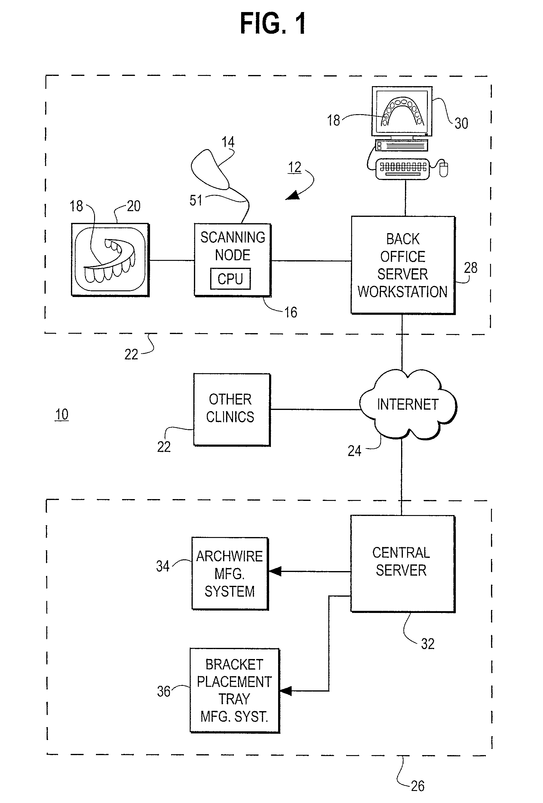
[0067] FIG. 1 is an illustration of an orthodontic care system 10 incorporating a hand-held scanner system 12. The scanner system 12 includes a hand-held scanner 14 that is used by the orthodontist to acquire three-dimensional information of the dentition and associated anatomical structures of a patient. The images are processed in a scanning node or workstation 16 having a central processing unit, such as a general-purpose computer. The scanning node 16, either alone or in combination with a back-office server 28, generates a three-dimensional computer model 18 of the dentition and provides the orthodontist with a base of information to plan treatment for the patient. The model 18 is displayed to the user on a monitor 20 connected to the scanning node 16.

[0068] The orthodontic care system consists of a plurality of orthodontic clinics 22 which are linked via the Internet or other suitable communications medium 24 (such as the public switched telephone networ...


PUM

PropertyMeasurementUnit
lengthaaaaaaaaaa
degrees of freedomaaaaaaaaaa
separation distanceaaaaaaaaaa

Abstract

A robotic bending apparatus for bending archwires and other types of elongate, bendable medical devices into a desired configuration includes a first gripping tool and a moveable gripping tool. The first gripping tool can be either fixed with respect to a base or table for the robot or positioned at the end of robot am. The moveable gripping tool is mounted to the end of a moveable robot arm having a proximal portion also mounted to the base. The robot preferably comprises a six axis bending robot, in which the distal end of the moveable arm can move relative to the fixed gripping tool about three translational axes and three rotational axes. The gripping tools preferably incorporate force sensors which are used to determine overbends needed to get the desired final shape of the archwire. The robot may also include a resistive heating system in which current flows through the wire while the wire is held in a bent condition to heat the wire and thereby retain the bent shape of the wire. A magazine for holding a plurality of straight archwires needing to be bent and a conveyor system for receiving the wires after the bending process is complete are also described. The robot bending system is able to form archwires with any required second and third order bends quickly and with high precision. As such, it is highly suitable for use in a precision appliance-manufacturing center manufacturing a large number of archwires (or other medical devices or appliances) for a distributed base of clinics.

Description

[0001] A. Field of the Invention[0002] This invention relates to a robot and method for automatically bending orthodontic archwires, retainers, or other orthodontic or medical devices into a particular shape.[0003] B. Description of Related Art[0004] In orthodontics, a patient suffering from a malocclusion is treated by affixing brackets to the surface of the teeth and installing an archwire in the slots of the brackets. The archwire and brackets are designed to generated a customized force system that applies forces to teeth, by which individual teeth are moved relative to surrounding anatomical structures into a desired occlusion. There are two approaches to designing an appropriate force system for a patient. One is based on a flat archwire and customized brackets, e.g., Andreiko et al., U.S. Pat. No. 5,447,432. The other is based on off-the shelf brackets and designing a customized archwire that has complex bends designed to move or rotate the teeth in the desired direction. Tra...

Claims


Application Information

Patent Timeline
Patent Type & Authority Applications(United States)
IPC IPC(8): A61C7/00A61C7/02B21F1/00B21F23/00B21F45/00B25J11/00G16H10/60G16H30/40
CPCA61C7/002A61C7/04A61C7/20A61C7/28B21F1/00B21F23/005B21F45/00B21F45/008B25J11/00G06Q50/24B33Y50/00B33Y80/00G16H30/40
Inventor BUTSCHER, WERNERRIEMEIER, FRIEDRICHRUBBERT, RUDGERWEISE, THOMASSACHDEVA, ROHIT
Owner ORAMETRIX
Why Eureka
Try Eureka