Belt connector
a technology of belt connectors and buckles, applied in the field of belt connectors, can solve problems such as troublesome re-connecting buckles while holding a baby
- Summary
- Abstract
- Description
- Claims
- Application Information
AI Technical Summary
Benefits of technology
Problems solved by technology
Method used
Image

Examples
first embodiment
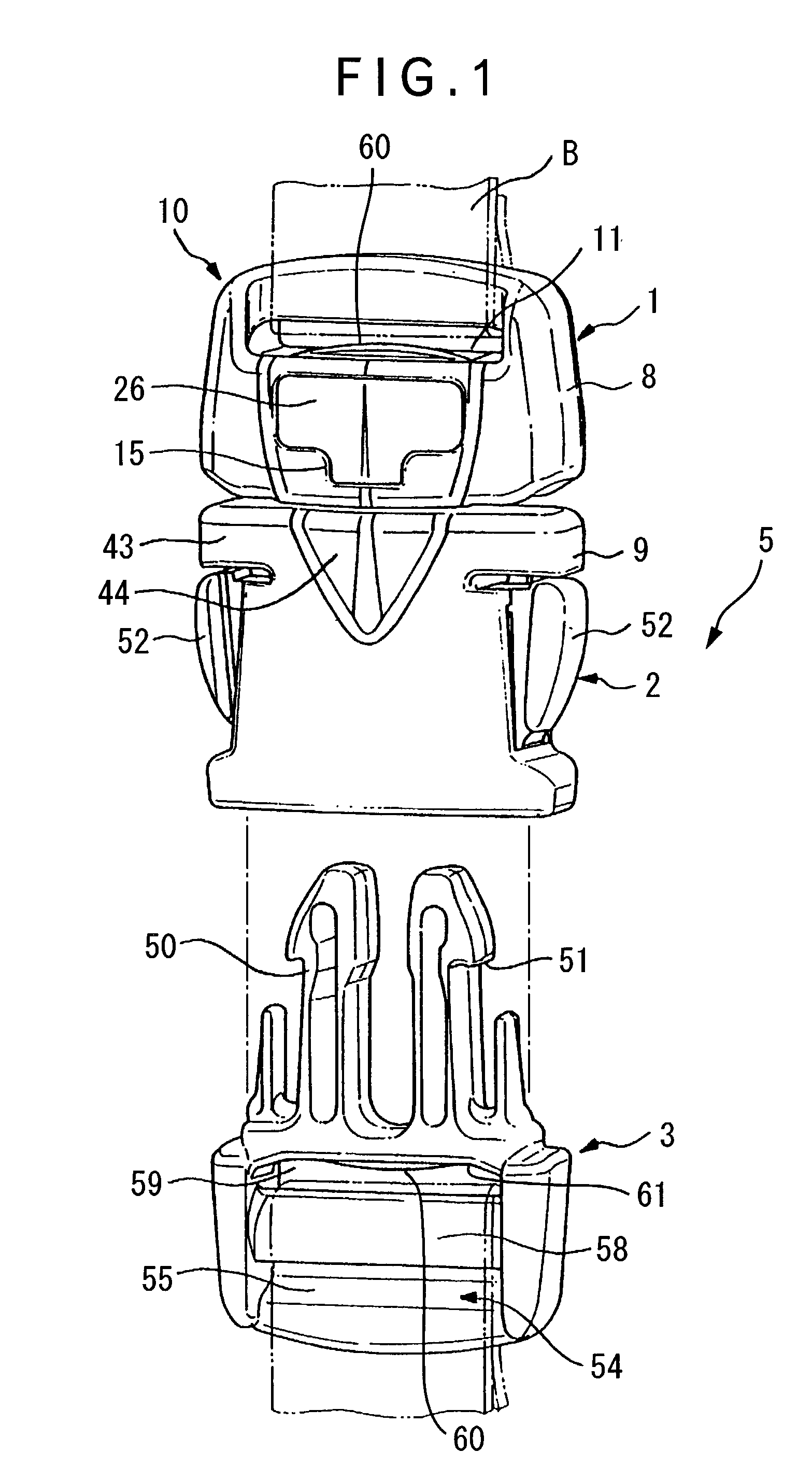
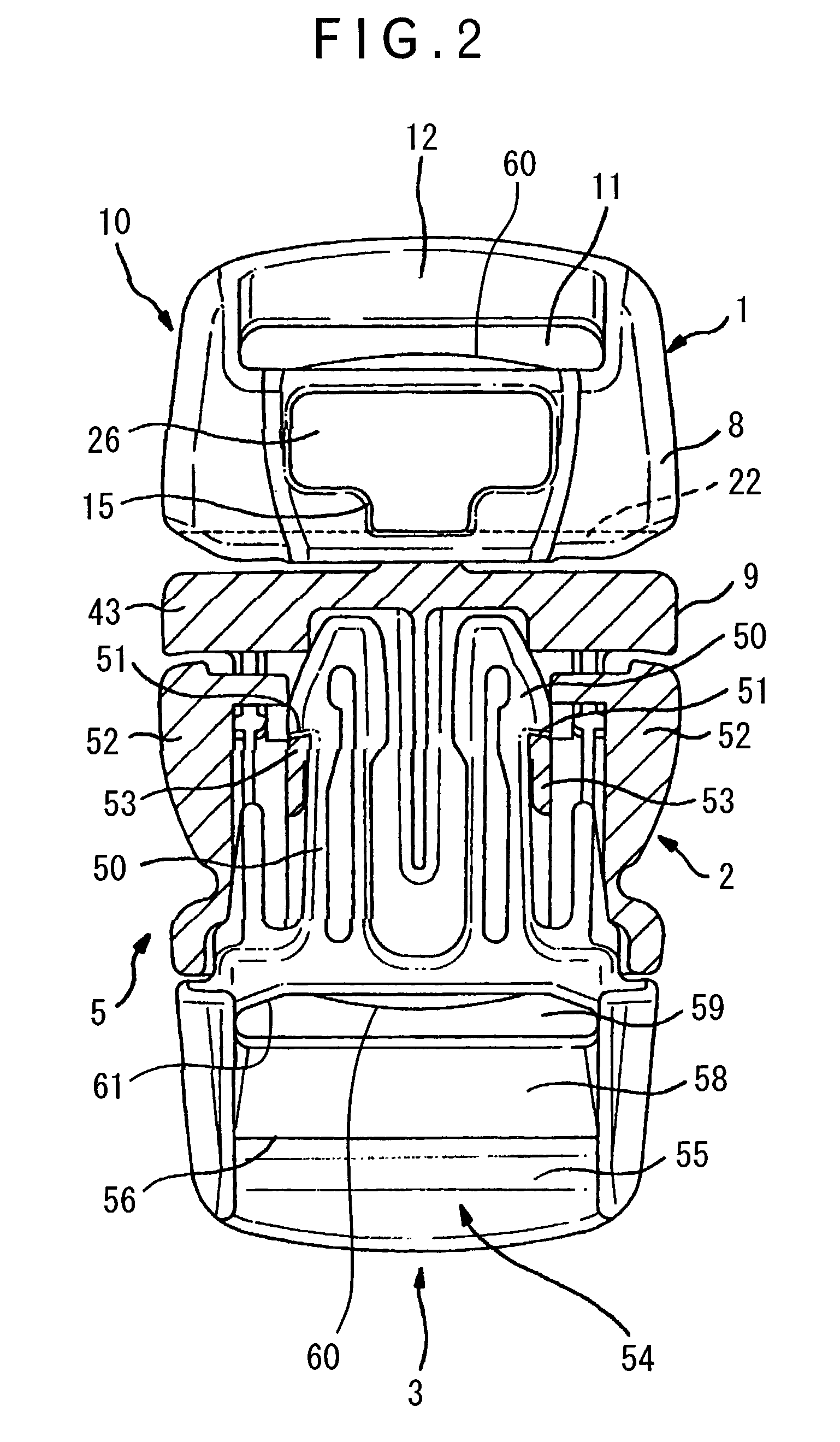
[0063] First Embodiment
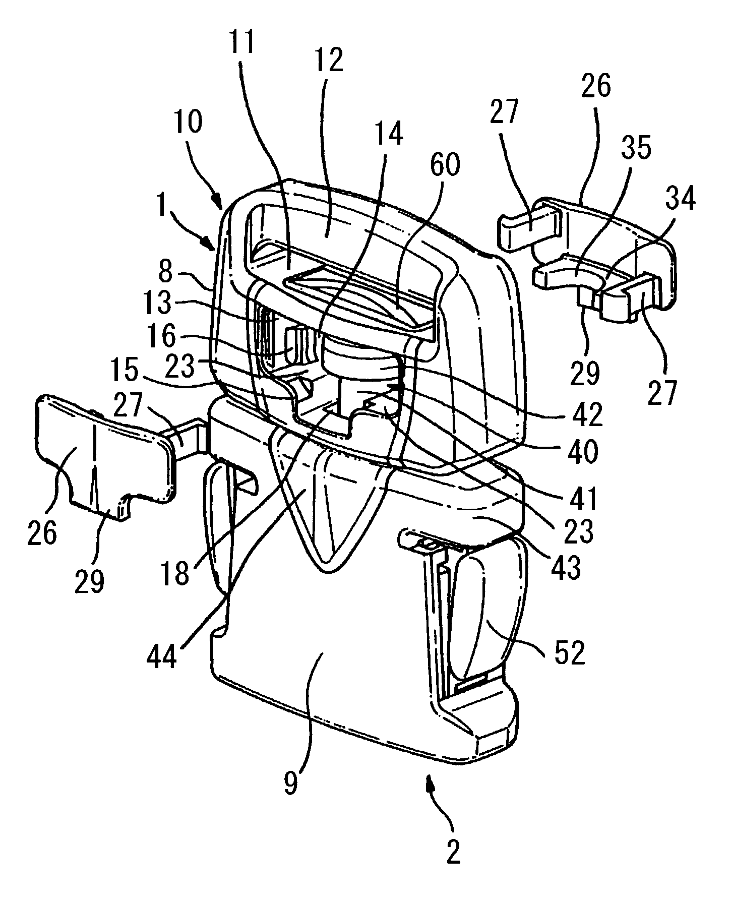
[0064] FIGS. 1 to 6 shows a male-female buckle 5 applied with a belt connector according to first embodiment of the present invention. As shown in FIG. 1, the belt connector has a flat body 8 as a first member 1 having a belt attachment 10 for attaching a belt B, a female body as a second member 2 and a third member 3 capable of being attachable and detachable relative to the second member 2 and having an insert leg 50 to be inserted to the second member 2 and a belt engaging portion 54 as another belt attachment. The body 8 of the first member 1 has an accommodating portion 13 composed of an accommodating space 19 having an opening 14 opened to front and back thereof for accommodating a rotary shaft 40 of the second member 2, the accommodating portion 13 having a slit 18 at the center of the lower side thereof for inserting the rotary shaft 40 projected on a body 9 of the second member 2. The opening 14 provided on the front and back side of the accommodating...
second embodiment
[0076] Second Embodiment
[0077] The belt connector according to second embodiment of the present invention shown in FIGS. 7 to 10 is the same as the above first embodiment except that the cover 26 and the retainer 34 are independent. As shown in FIG. 7, the retainer 34 is formed in a C-shaped bearing 35 by forming a slit 36 at a part of a ring to be fitted to the rotary shaft 40. A rotation-stop projection 37 extending downward is provided on the opposite side of the slit 36 to be fitted to the groove 15 formed on the accommodating portion 13 in a concave fashion.
[0078] On the other hand, as shown in FIG. 8, the cover 26 has the engaging pieces 27 on both sides of a flat plate of approximate T-shape provided in a vertically alternate manner, outside-facing engaging claws 28 being provided on the distal end of the engaging piece 27 to be engaged with the engaging projection 16 provided on the sidewall 20 of the accommodating portion 13.
[0079] The retainer 34 and the cover 26 are attac...
third embodiment
[0080] Third Embodiment
[0081] The belt connector according to third embodiment of the present invention shown in FIGS. 11 to 14 is different from the above-described embodiments in the arrangement of the retainer 34 and the cover 26. As shown in FIG. 14, a concave portion 17 penetrating from the belt attachment hole 11 to the inside, i.e. toward the rotary shaft 40, is provided on the body 8 of the belt attachment 10 of the first member 1. The lower side of the body 8 is gently raised toward the body 9 of the second member 2, at which a core hole 19 for molding the rotary shaft 40 is formed. The core of the injection molding process is inserted to the concave portion 17 and a gap 25 around the rotary shaft 40 from front and back direction to mold a part of the neck portion 41 of the rotary shaft 40 and the bulging head 42. Further, Another core is inserted to the core hole 19 at the raised portion from right and left direction to form the rest of the neck portion of the rotary shaft...
PUM
 Abstract
Description
Claims
Application Information
 - R&D
- Intellectual Property
- Life Sciences
- Materials
- Tech Scout
- Unparalleled Data Quality
- Higher Quality Content
- 60% Fewer Hallucinations
Browse by: Latest US Patents, China's latest patents, Technical Efficacy Thesaurus, Application Domain, Technology Topic, Popular Technical Reports.
© 2025 PatSnap. All rights reserved.Legal|Privacy policy|Modern Slavery Act Transparency Statement|Sitemap|About US| Contact US: help@patsnap.com