Vehicle crash wall

Inactive Publication Date: 2003-05-01
KRAMER RICK
View PDF0 Cites 24 Cited by
  • Summary
  • Abstract
  • Description
  • Claims
  • Application Information

AI Technical Summary

Problems solved by technology

The prior art contains examples of these concepts but fail to produce the desired result due to the stationary nature of a crash wall.
This results in serious injury to the driver and complete destruction of the vehicle.
Although this construction is very strong, it does nothing to reduce the crash impact to the car and driver, help control the car after the impact or diminish the amount of flying debris.
This puts great stress on the outer structure.
This causes a tremendous amount of pressure to be exerted against the points where the beams connect to the outer wall and sea wall.
Wooden walls could not withstand the tremendous force of the crash.
This resulted in vehicles ripping through their boards, careening into the spectator stands at racing events, total destruction of the vehicle and serious injury to the driver.
Although the crash force is diminished, the resulting crash site is heavily littered with thousands of pieces of the plastic wall and car.
The cleanup takes hours and the wall has to be replaced after each crash.
The flyin

Method used


Image

  • Vehicle crash wall
  • Vehicle crash wall
  • Vehicle crash wall

Examples


Embodiment Construction

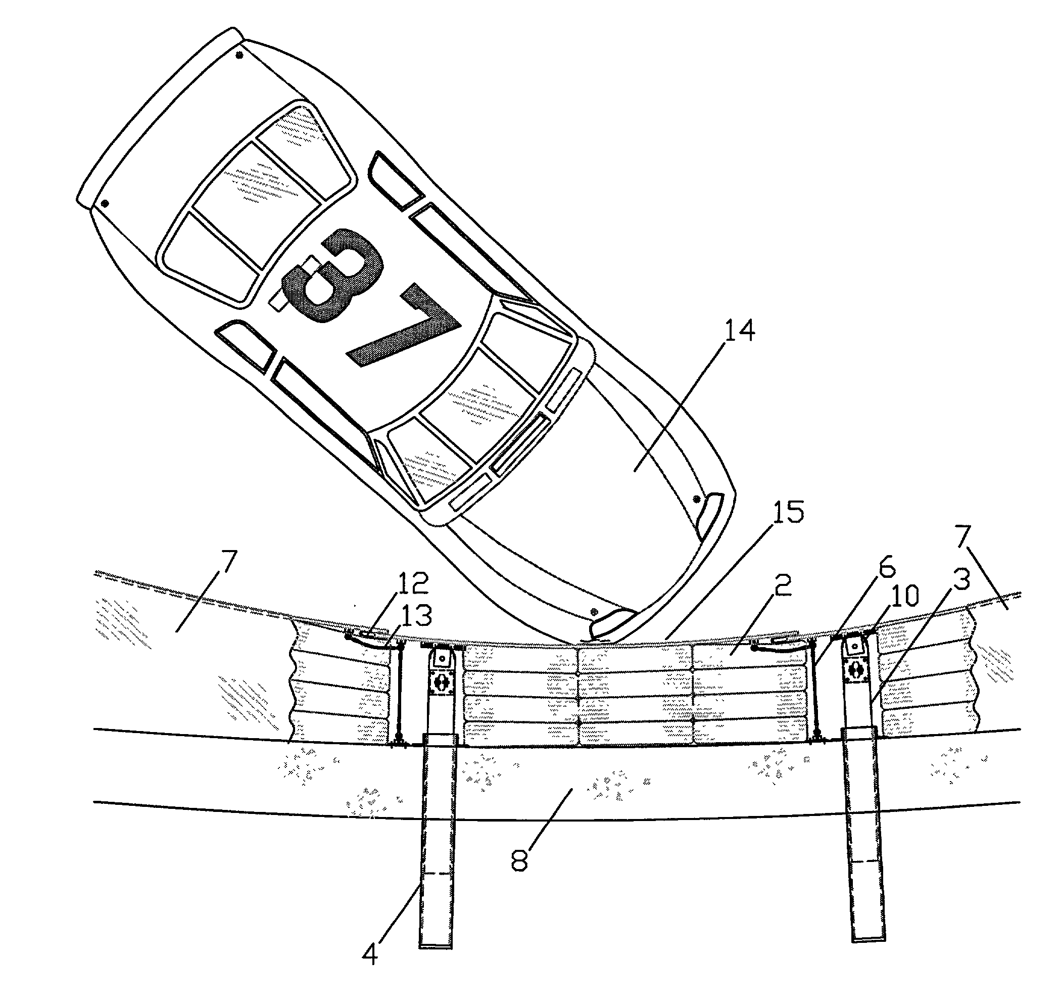
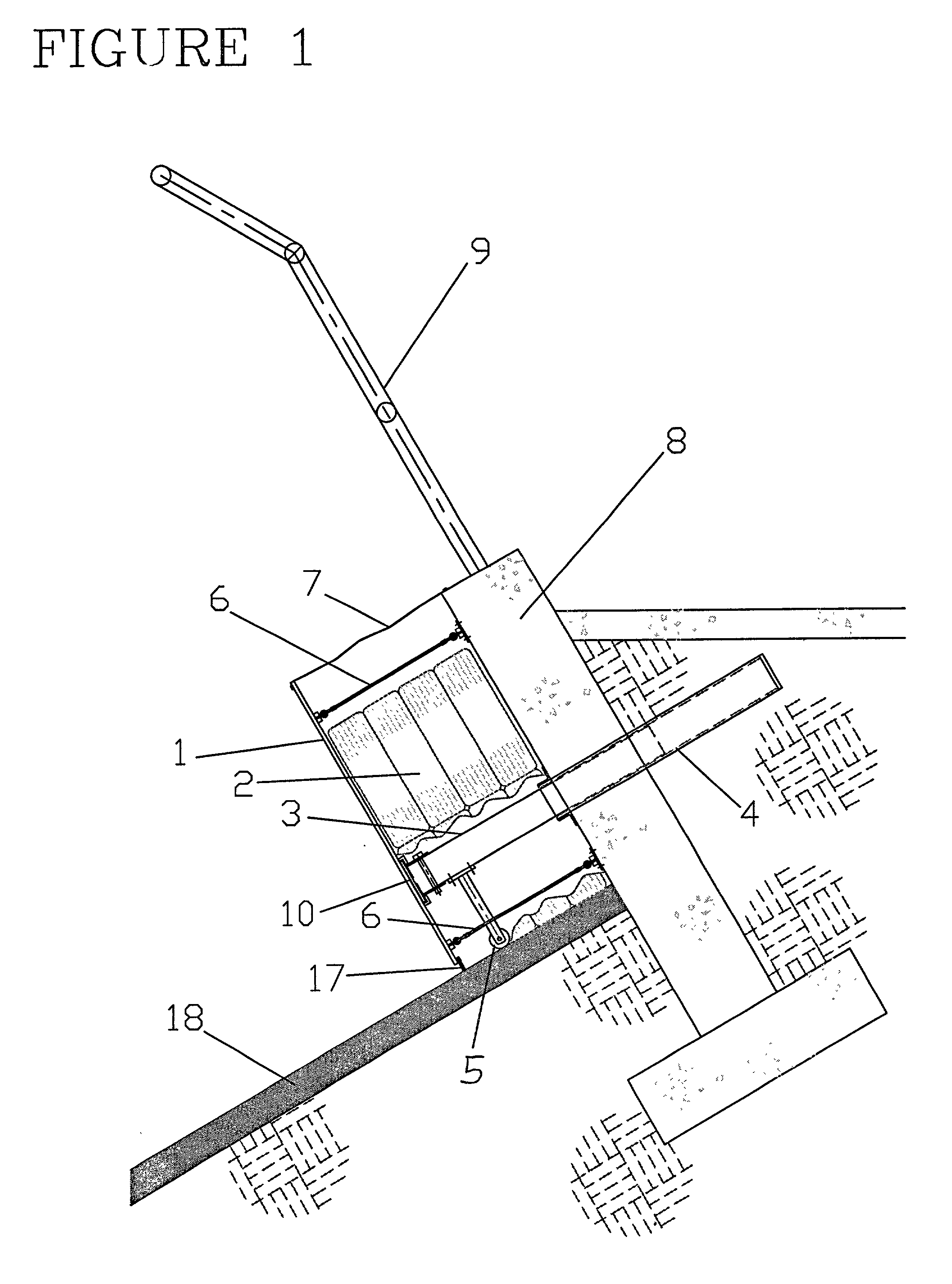
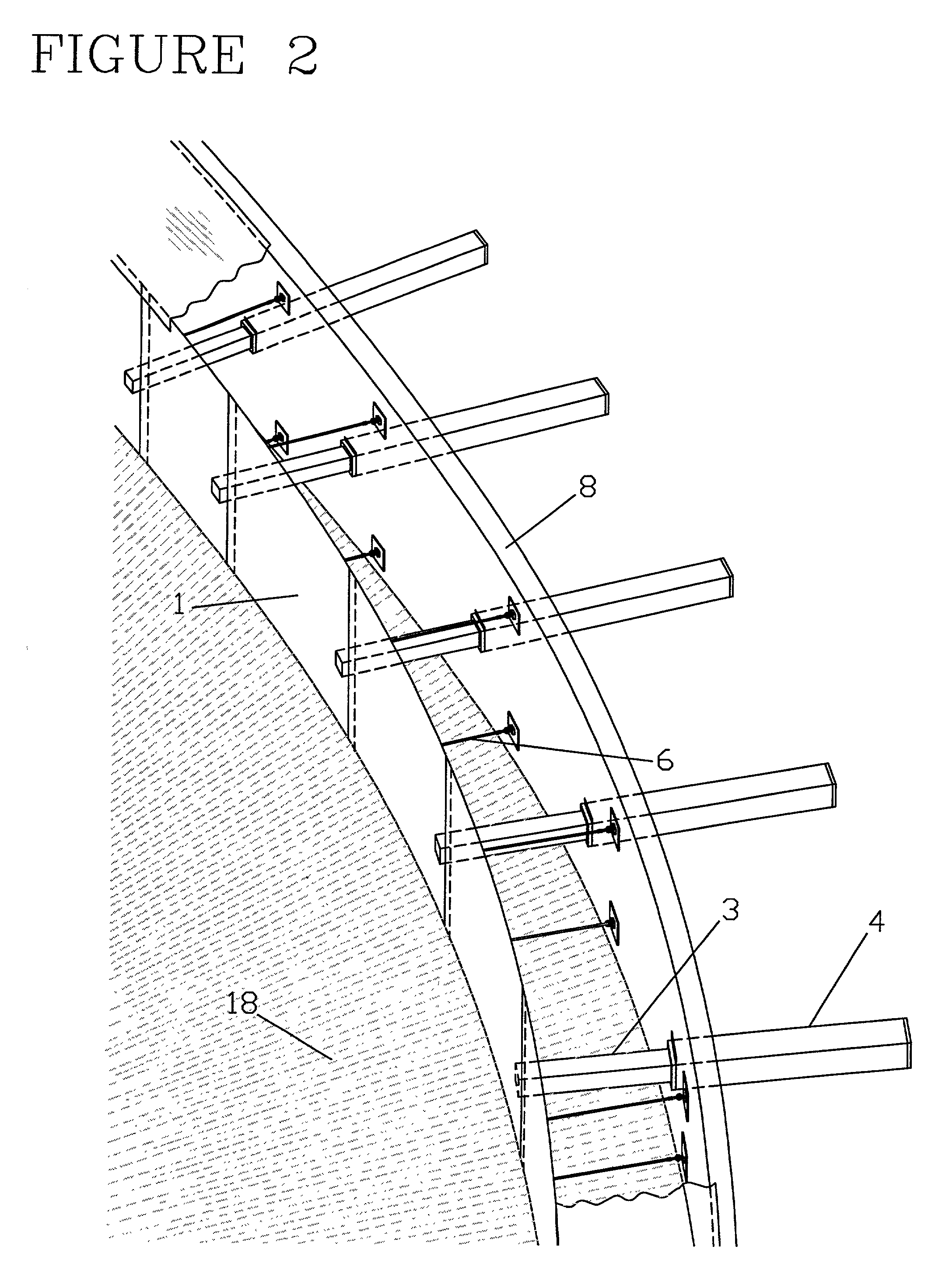
[0021] Operation and use of the vehicle crash wall is simple and straightforward. It has over-lapping metal impact plates which are attached to a retaining wall by anchoring cables and a plate stabilizer tube. Impact absorbent filler material is located between the impact plate and retaining wall cushioning the impact and helping to uniformly dissipate the impact force along other plates.

[0022] It may be utilized in many settings, including racetracks, freeways, highways, bridges and any area frequented by vehicles. The impact absorbent material is composed of rubber tires but may be made from any other material suitable for this purpose.

[0023] In FIG. 1, the impact plate, 1, is located horizontal to the retaining wall, 8, which runs parallel to a fence, 9, that catches debris. Located at the bottom of the impact plate, 1, is a debris brush, 17. The retaining wall, 8, has a female receiving tube, 4, imbedded through the middle of said retaining wall, 8, which extends behind said ret...


PUM


Abstract

A vehicle crash wall with a series of overlapping metal plates attached to a retaining wall by means of a metal sleeve inserted into a female receiving tube. Located between the metal plates and retaining wall is an impact absorbing material. The metal sleeves, 3, are perpendicularly attached to the metal plates, 1, by inserting them into slip joints, 16, and inserting metal pins, 11, vertically through the top of said metal sleeves and into swivel hinges, 10, located beneath said slip joints. The female receiving tubes, 4, are located inside the middle of the retaining wall, 8, perpendicularly extending approximately half-way behind said retaining wall. Said metal sleeves are vertically supported by rollers arms, 5. Said metal plates are perpendicularly supported by cable hold backs, 6, and horizontally by support cables, 13. The force of the impact is evenly dissipated along the length of metal plates and energy absorbent material. This dramatically reduces the risk of injury to the driver and damage to his vehicle and the wall.

Description

BACKGROUND--FIELD OF INVENTION[0001] This invention relates to a new and innovative vehicle crash wall. It can be used at a racetrack, along dangerous sections of public highways or any location where vehicles operate. It dramatically reduces the risk of serious injury to the driver and damage to the vehicle. A series of metal impact plates are attached to a retaining wall through a novel system of cables, slipjoints and plate stabilizers. The force of the impact is absorbed along the entire series of plates through a combination of filler material, located between the plate and retaining wall, and the unique operation of the plate stabilizers. This drastically reduces the force of the impact and significantly diminishes the damage to the vehicle, driver and metal impact plates. After the impact, the vehicle can continue its course on a parallel axis to the wall thus preventing itself from bouncing back into oncoming traffic and causing further accidents to other vehicles.BACKGROUND...

Claims


Application Information

Patent Timeline
IPC IPC(8): E01F15/14
CPCE01F15/145
Inventor KRAMER, RICK
Owner KRAMER RICK
Why Eureka
Try Eureka