Magnetic displacement sensor device and method for detecting displacements

a technology of magnetic displacement sensor and displacement sensor, which is applied in the direction of measuring device, electrical/magnetically converting sensor output, instruments, etc., can solve the problems of increasing the overall device size, increasing the cost and size of the overall device, and failing to completely prevent the interference phenomenon

Inactive Publication Date: 2003-05-08
SANKYO SEIKI MFG CO LTD
View PDF7 Cites 18 Cited by
  • Summary
  • Abstract
  • Description
  • Claims
  • Application Information

AI Technical Summary

Problems solved by technology

In such cases, magnetic fields generated by various magnetic displacement sensors cause mutual magnetic influences, which generate beat noise due to mutual interference between magnetic fields, and favorable detection operations cannot take place.
However, when magnetic shield members are used, the overall device size becomes larger due to the need to create space to accommodate the magnetic shield members, and the method still fails to completely prevent the interference phenomenon between the magnetic fields.
When different drive frequencies are used for various magnetic displacement sensors, drive devices for different frequencies must be provided, which increases the cost and size of the overall device.

Method used


Image

  • Magnetic displacement sensor device and method for detecting displacements
  • Magnetic displacement sensor device and method for detecting displacements
  • Magnetic displacement sensor device and method for detecting displacements

Examples


Embodiment Construction

[0029] Embodiments of the present invention are described below in detail with reference to the accompanying drawings.

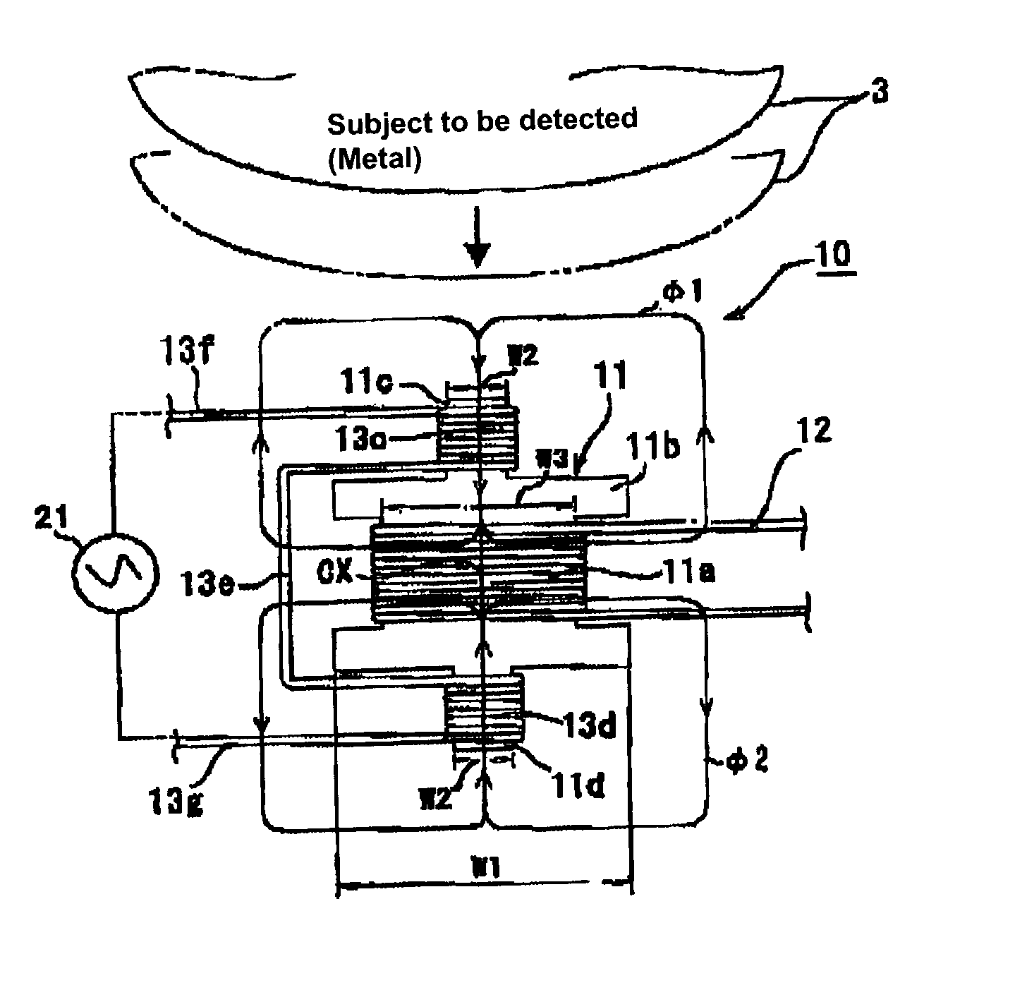
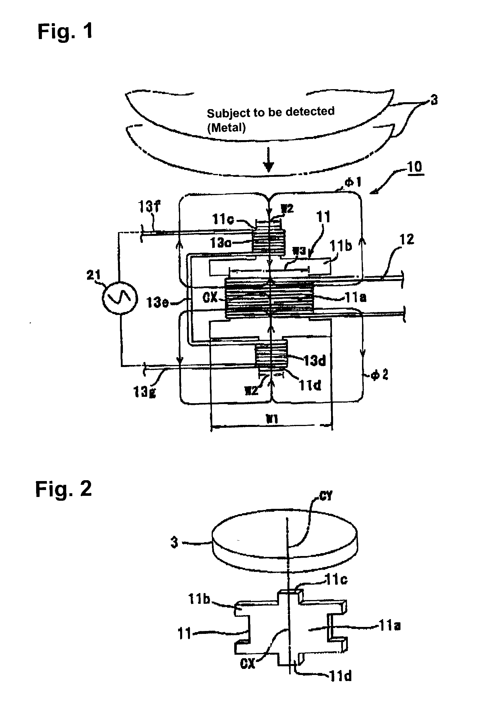
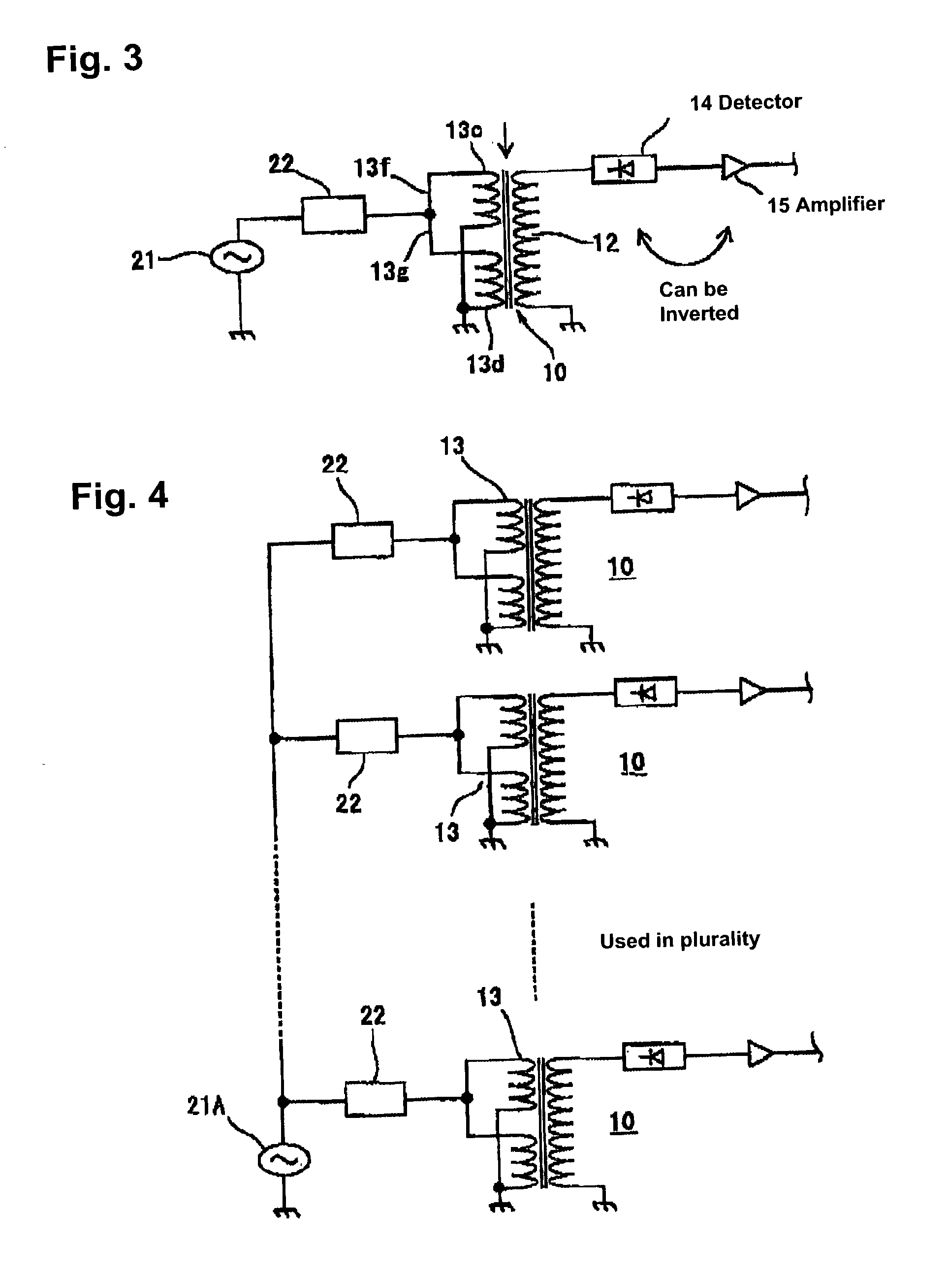
[0030] A magnetic displacement sensor device in accordance with an embodiment of the present invention includes a plurality of separately excited magnetic displacement sensors 10 that are placed in close proximity to a detection subject 3, as shown in FIGS. 9 and 10 described above. The distance between each of the magnetic displacement sensors 10 and the detection subject 3 is measured based on a detection output from each of the plurality of the magnetic displacement sensors 10, and information such as the position, tilt and thickness of the detection subject 3 is obtained based on such measurement results. To describe the structure of such a magnetic displacement sensor device, the structure of one of the magnetic displacement sensors 10 itself will be described first.

[0031] In the so-called separately excited magnetic displacement sensor 10 according to the prese...


PUM


Abstract

A magnetic displacement sensor device includes a plurality of magnetic displacement sensors, each of the magnetic displacement sensors having at least one coil wound thereon, and a single common excitation oscillator connected to each of the coils wound on the respective magnetic displacement sensors. Each of the coils are excited at the same oscillatory frequency and in the same phase by the single common excitation oscillator.

Description

[0001] 1. Field of the Invention[0002] The present invention relates to magnetic displacement sensor devices, in which a plurality of magnetic displacement sensors are arranged and configured to detect their relative positions to detection subjects. The present invention also relates to a method for detecting displacements.[0003] 2. Description of Related Art[0004] Generally, magnetic displacement sensors are widely used in various types of devices that identify the unevenness or the material of detection subjects, such as coins, in such devices as vending machines, ticket vending machines and ATMs, or in motor rotation drive control devices. Conventional magnetic displacement sensors are what are called eddy current type, such as shown in FIG. 11. A current is applied to a coil 2 wound around a core body 1, which is rod-shaped, to generate a magnetic flux .phi.r for detection purposes. A metallic detection subject 3 and the core body 1 are moved relatively close to and far away fro...

Claims


Application Information

Patent Timeline
Patent Type & Authority Applications(United States)
IPC IPC(8): G01B7/00G01D5/20G07D5/08
CPCG01D5/2046
Inventor MOMOSE, SHOGO
Owner SANKYO SEIKI MFG CO LTD
Why Eureka
Try Eureka