System and method for locating a fault on ungrounded and high-impedance grounded power systems

a technology of high-impedance grounded power system and system, which is applied in the direction of fault location by conductor type, structural/machine measurement, instruments, etc., can solve the problems of more difficult to locate, devices do not determine the fault location, and ground faults are difficult to locate in ungrounded or high-impedance grounded systems

Inactive Publication Date: 2003-05-08
ABB INC
View PDF0 Cites 90 Cited by
  • Summary
  • Abstract
  • Description
  • Claims
  • Application Information

AI Technical Summary

Benefits of technology

0016] These and other features of the present invention will be more fully set forth hereinafter.

Problems solved by technology

Unfortunately, ground faults are hard to locate in ungrounded or high-impedance grounded systems since the ground current for the first fault is much smaller than the load currents.
Additionally, some faults are intermittent, making them even more difficult to locate.
However, these types of devices do not determine a fault location; rather, these devices only indicate the occurrence of a fault and indicate the phase on which the fault has occurred.
However, these systems do not determine a specific fault location; rather, these systems provide a general fault location.
However, the measured voltages are often too small to measure reliably, which may introduce errors into the determined fault location.
Moreover, standard relays typically do not have many input channels for voltages.
Therefore, non-standard relays may be required to implement this system.
This can take a great deal of time and can disrupt the operation of an industrial site significantly.
Moreover, the measurements may not be accurate because the measured impedance is typically very low; often low enough that the contact resistance of an impedance measuring device may introduce significant errors into the measurement.
Fault location is also possible using directional measurements as in a high-voltage transmission system, but these products are generally too complex and expensive for use in an industrial environment.

Method used


Image

  • System and method for locating a fault on ungrounded and high-impedance grounded power systems
  • System and method for locating a fault on ungrounded and high-impedance grounded power systems
  • System and method for locating a fault on ungrounded and high-impedance grounded power systems

Examples


Embodiment Construction

[0031] The present invention is directed to a system and method for calculating a fault location in a power distribution system based on an injected signal, a network model, at least one current measurement corresponding to the injected signal and at least one predetermined relative impedance.

[0032] Certain terminology may be used in the following description for convenience only and is not considered to be limiting. For example, the words "left", "right", "upper", and "lower" designate directions in the drawings to which reference is made. Likewise, the words "inwardly" and "outwardly" are directions toward and away from, respectively, the geometric center of the referenced object. The terminology includes the words above specifically mentioned, derivatives thereof, and words of similar import.

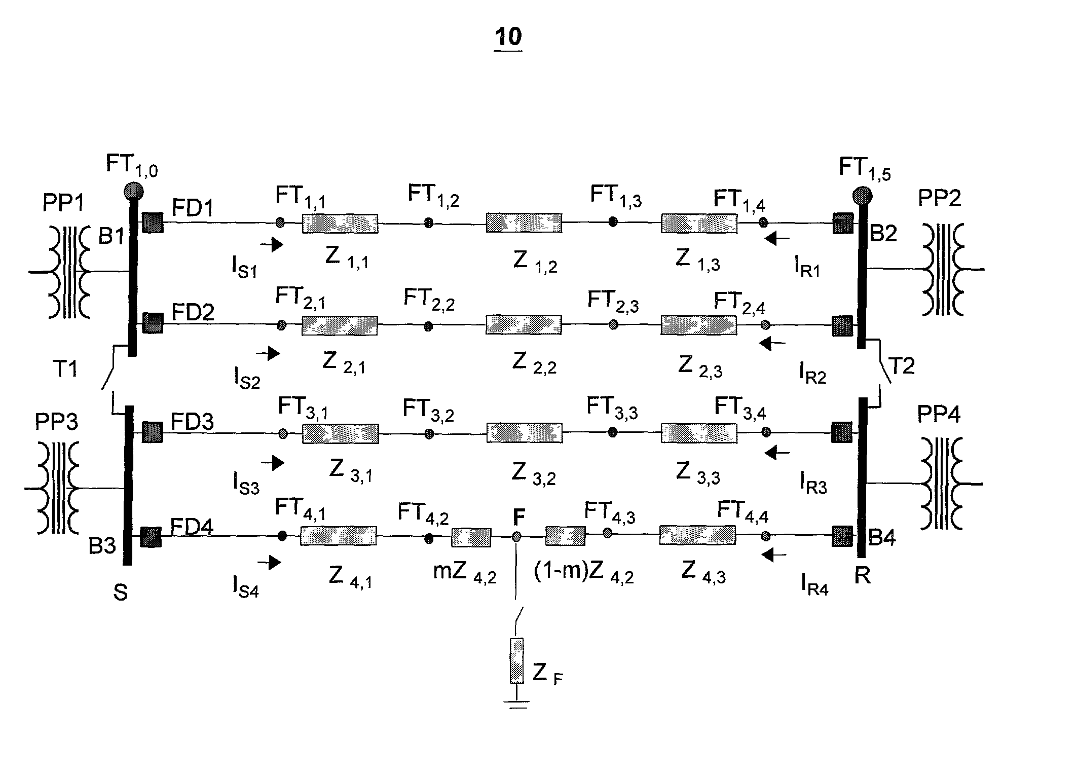
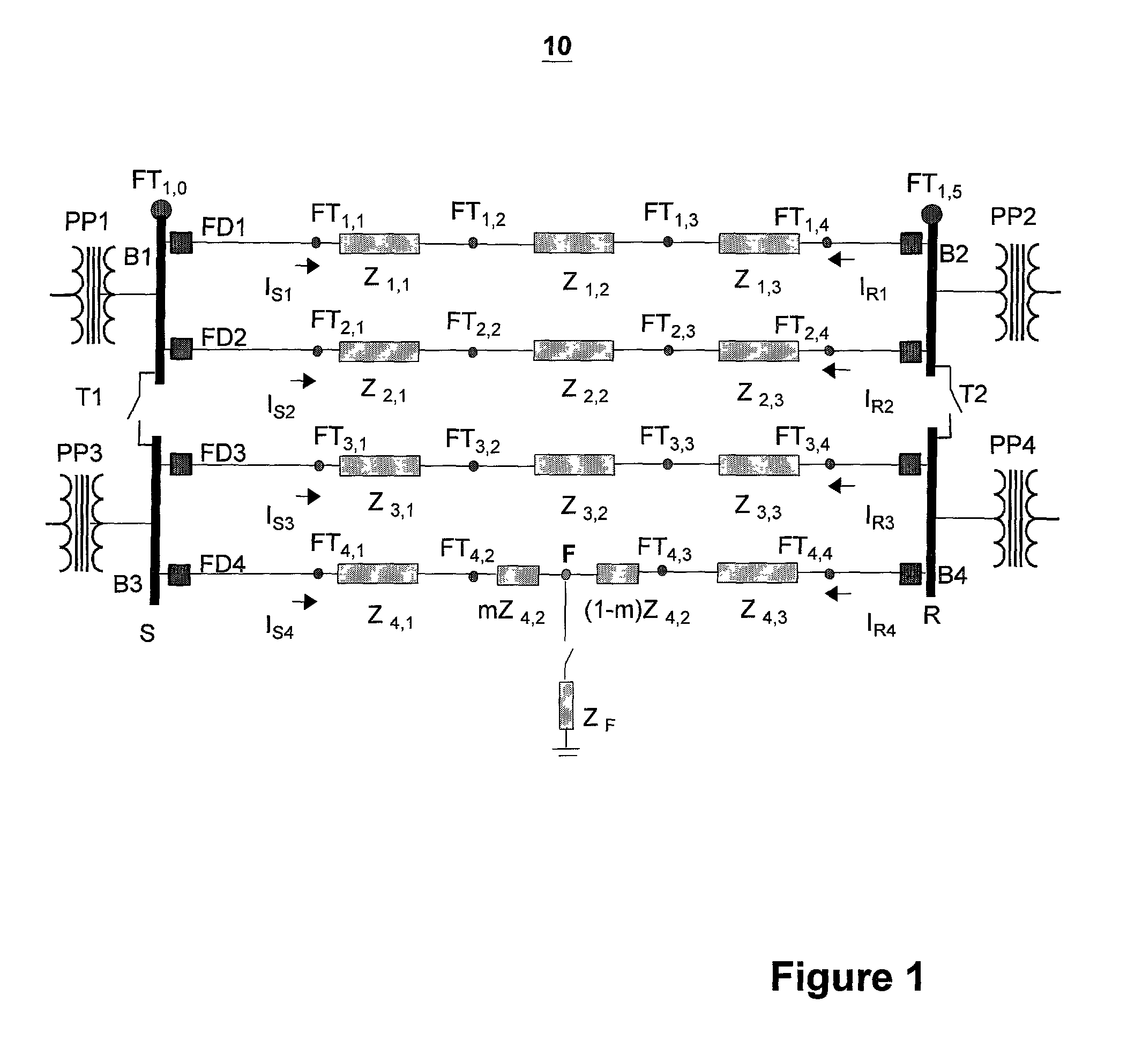
[0033] FIG. 1 illustrates an exemplary looped power distribution system having a fault node F. As shown in FIG. 1, the power distribution system 10 includes a sending node S and a receiving n...


PUM


Abstract

A fault is located in a power distribution system having a line frequency. The power distribution system includes a plurality of phases, at least one feeder, and each feeder includes at least one segment. The fault is located by detecting a faulted phase from the plurality of phases of the power distribution system. A measurement signal having a measurement frequency is injected into the detected faulted phase, the measurement frequency being a different frequency than the line frequency. The fault location is determined for a selected segment based on at least one measured residual current corresponding to the injected signal and a predetermined relative impedance of the power distribution system.

Description

[0001] The present invention relates to a system and method for locating a fault in a power system, more particularly, an ungrounded or high-impedance grounded power distribution system.[0002] Power distribution systems carry current from transformers and / or generating sources to electrical loads. A power distribution system typically includes three phases, however, a power distribution system may also include one phase, or some other number of phases. Additionally, the power distribution system may be grounded, ungrounded, or high impedance grounded.[0003] Ungrounded and high-impedance grounded distribution systems are used in a number of industrial power distribution systems. The advantage of these systems is that they can continue operation after a single ground fault occurs, thereby eliminating the need for immediate shutdown. Unfortunately, ground faults are hard to locate in ungrounded or high-impedance grounded systems since the ground current for the first fault is much smal...

Claims


Application Information

Patent Timeline
Patent Type & Authority Applications(United States)
IPC IPC(8): G01M99/00G01R31/08
CPCY04S10/522G01R31/086Y04S10/52
Inventor LUBKEMAN, DAVIDGORMAN, MICHAEL J.HART, DAVID G.
Owner ABB INC
Why Eureka
Try Eureka