Nut plate

a nut plate and rivetless technology, applied in the direction of threaded fasteners, fastening means, dowels, etc., can solve the problems rivetless nut plates, and prone to flaring, so as to simplify the installation of rivetless nut plates

Inactive Publication Date: 2003-05-15
SPS TECH LLC
View PDF16 Cites 33 Cited by
  • Summary
  • Abstract
  • Description
  • Claims
  • Application Information

AI Technical Summary

Benefits of technology

[0013] A primary object of the invention is to provide a rivetless nut plate which will simplify the installation of rivetless nut plates to workpieces.
[0014] An object of the invention is to provide a rivetless nut plate which utilizes a novel tooling concept to speed up the installation of the nut plate to the workpiece and which ensures proper engagement of the sleeve of the nut plate to the workpiece.
[0015] Another object of the invention is to provide a rivetless nut plate which will greatly expand the usage of rivetless nut plate in aerospace applications as well as in commercial industry.

Problems solved by technology

The installation of rivetless nut plates with tooling of present designs, however, such as those discussed in U.S. Pat. No. 4,732,518, is cumbersome, slow, complicated, costly and often non-functional.
The flaring of rivetless nut plates is also disadvantageous for many reasons, such as complicated tooling, special aperture preparation (such as counter-bore and counter-sink) to achieve flush installation, grip length limitations, the creation of gaps between the sleeve and the walls of the workpiece, and longer length, thus making the rivetless nut plate a relatively heavy component.
The parts for this design are very expensive, installation is costly and cumbersome, and hole preparation needs to be very precise.
Thus, the overall cost of this design is very high and application is thereby limited.
There are also reports in the field that because of the required heavy expansion the receiving structure can deform beyond acceptable limits, thereby causing damage and rejection of the hole structure.

Method used


Image

  • Nut plate
  • Nut plate
  • Nut plate

Examples


Embodiment Construction

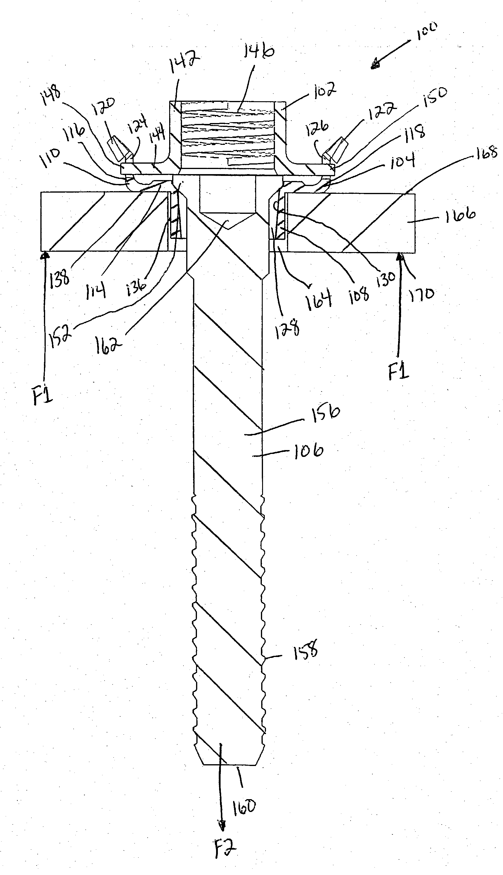
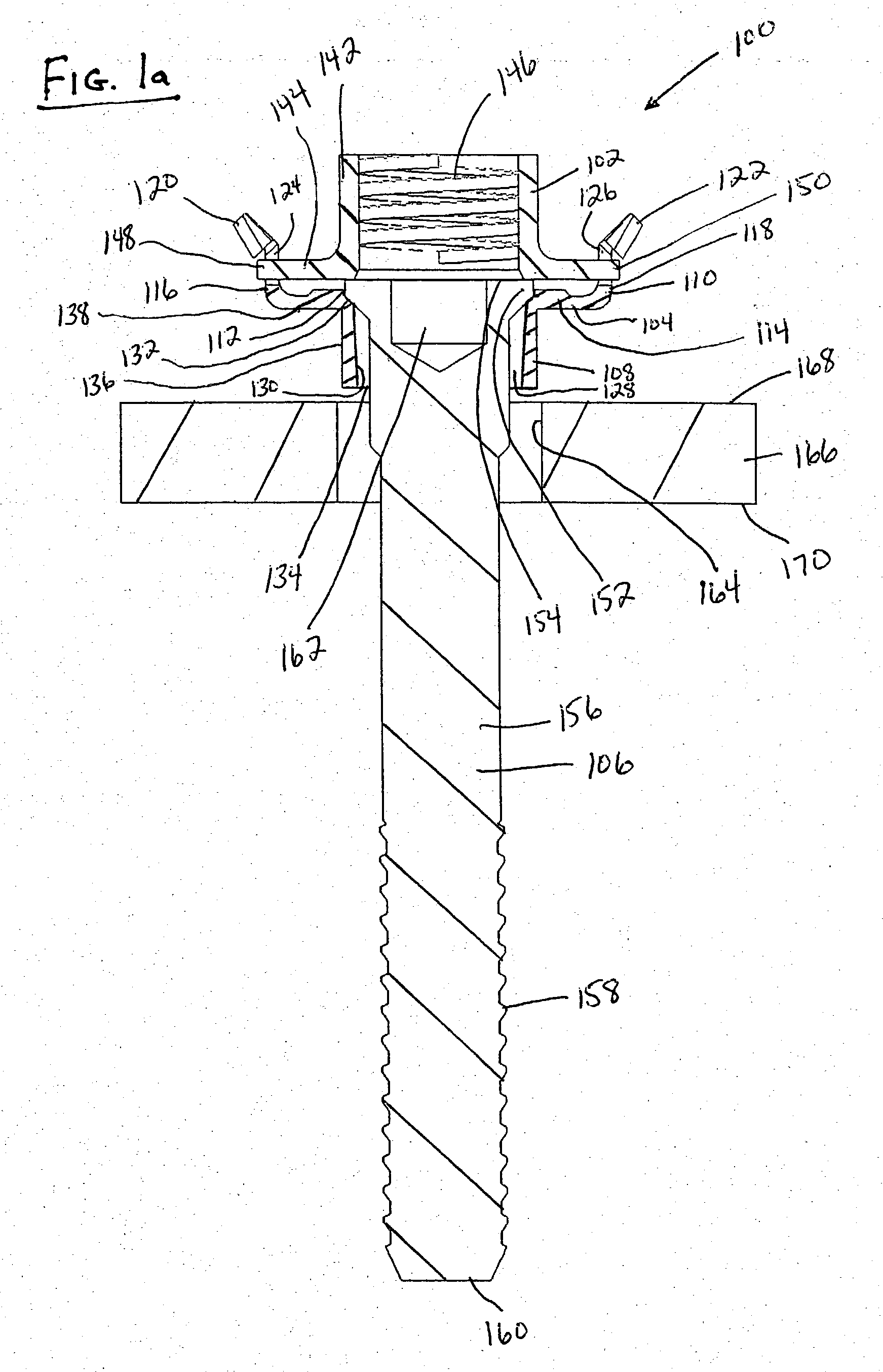
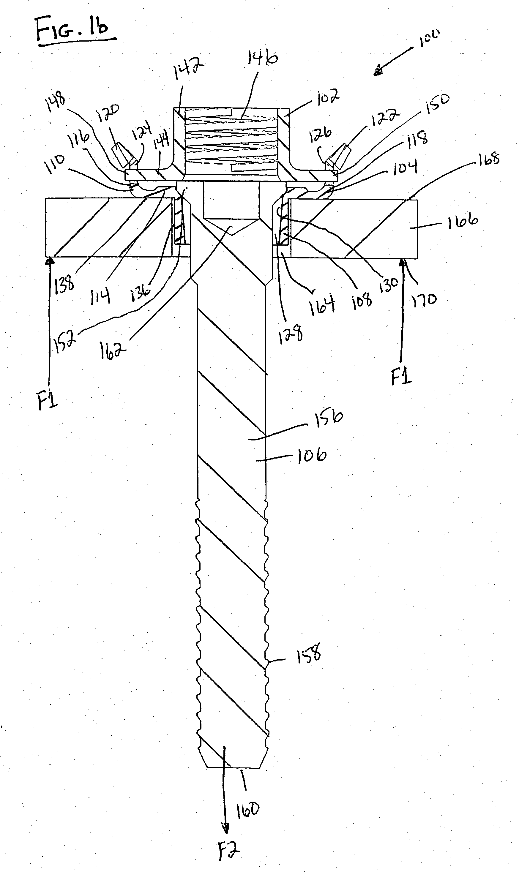
[0045] While this invention may be susceptible to embodiment in different forms, there is shown in the drawings and will be described herein in detail, specific embodiments with the understanding that the present disclosure is to be considered an exemplification of the principles of the invention, and is not intended to limit the invention to that as illustrated.

[0046] A first embodiment of a nut plate 100 is shown in FIGS. 1-6, a second embodiment of the nut plate 200 is shown in FIGS. 7-9, and a third embodiment of the nut plate 300 is shown in FIGS. 10-16. Like elements are denoted with like reference numerals with the first embodiment being in the one hundreds, the second embodiment being in the two hundreds, and the third embodiment being in the three hundreds.

[0047] Attention is now directed to the nut plate 100 of the first embodiment of the invention as illustrated in FIGS. 1-6. The nut plate 100 of the first embodiment includes a nut 102, a holding bracket 104 and a stem 10...


PUM

PropertyMeasurementUnit
thicknessaaaaaaaaaa
thicknessaaaaaaaaaa
wall thicknessaaaaaaaaaa

Abstract

The invention provides a rivetless nut plate including a nut, a holding bracket having tubular and bracket portions, and a stem having an enlarged head. The stem is positioned within an aperture of the tubular portion such that the head is resting on a shoulder within the bracket aperture. The tubular portion is positioned within an aperture of a workpiece, such that the bracket portion rests on top of the workpiece. The nut is retained within the bracket portion. Force is applied to a bottom of the workpiece and another opposite force is applied to the stem such that the head expands the tubular portion radially outwardly such that lobes on the tubular portion become embedded into the wall of the workpiece, thereby securing the nut plate to the workpiece. The holding bracket could also be formed of two separate elements, a sleeve having a tubular portion and a bracket.

Description

CROSS-REFERENCE[0001] This patent application claims the benefit of domestic priority of U.S. Provisional Application Serial No. 60 / 345,105, filed Nov. 9, 2001, and entitled "Nutplate".[0002] The present invention relates to a rivetless nut plate typically used in the aerospace industry.[0003] Nut plates are used for attaching structural and non-structural components together in both aerospace and commercial applications. There are many different design configurations of nut plates being used today. Two major classes are riveted nut plates and flared rivetless nut plates.[0004] In riveted nut plates, two or more rivets are employed for attaching the body of the nut plates to the workpiece.[0005] Rivetless nut plates are composed fundamentally of three components: a nut element, a holding bracket, and an attachment sleeve. The method of attachment and fixing of these nut plates to workpieces is based on two major features:[0006] (1) The insertion of the sleeve into an aperture of a w...

Claims


Application Information

Patent Timeline
Patent Type & Authority Applications(United States)
IPC IPC(8): F16B37/04F16B37/06
CPCB23P9/025F16B37/044F16B37/065Y10T29/49837Y10T29/49963Y10T29/49948Y10T29/49835Y10T29/49956F16B37/04
Inventor TOOSKY, RAHMATOLLAH F.
Owner SPS TECH LLC
Why Eureka
Try Eureka