
Hardware interlock mechanism using a watchdog timer

a technology of hardware interlocking and watchdog timer, applied in the field of computing systems, can solve the problems of irritating users and slowing productivity during long boot tim

Inactive Publication Date: 2003-05-22
GLOBALFOUNDRIES INC
View PDF12 Cites 31 Cited by
  • Summary
  • Abstract
  • Description
  • Claims
  • Application Information

AI Technical Summary

Problems solved by technology

System operation errors may also be alerts, such as memory errors, data device errors, data controller errors, CPU electrical characteristic mismatches, etc.
Operating system (OS) events may also generate alerts, such as OS boot failure or OS timeouts.
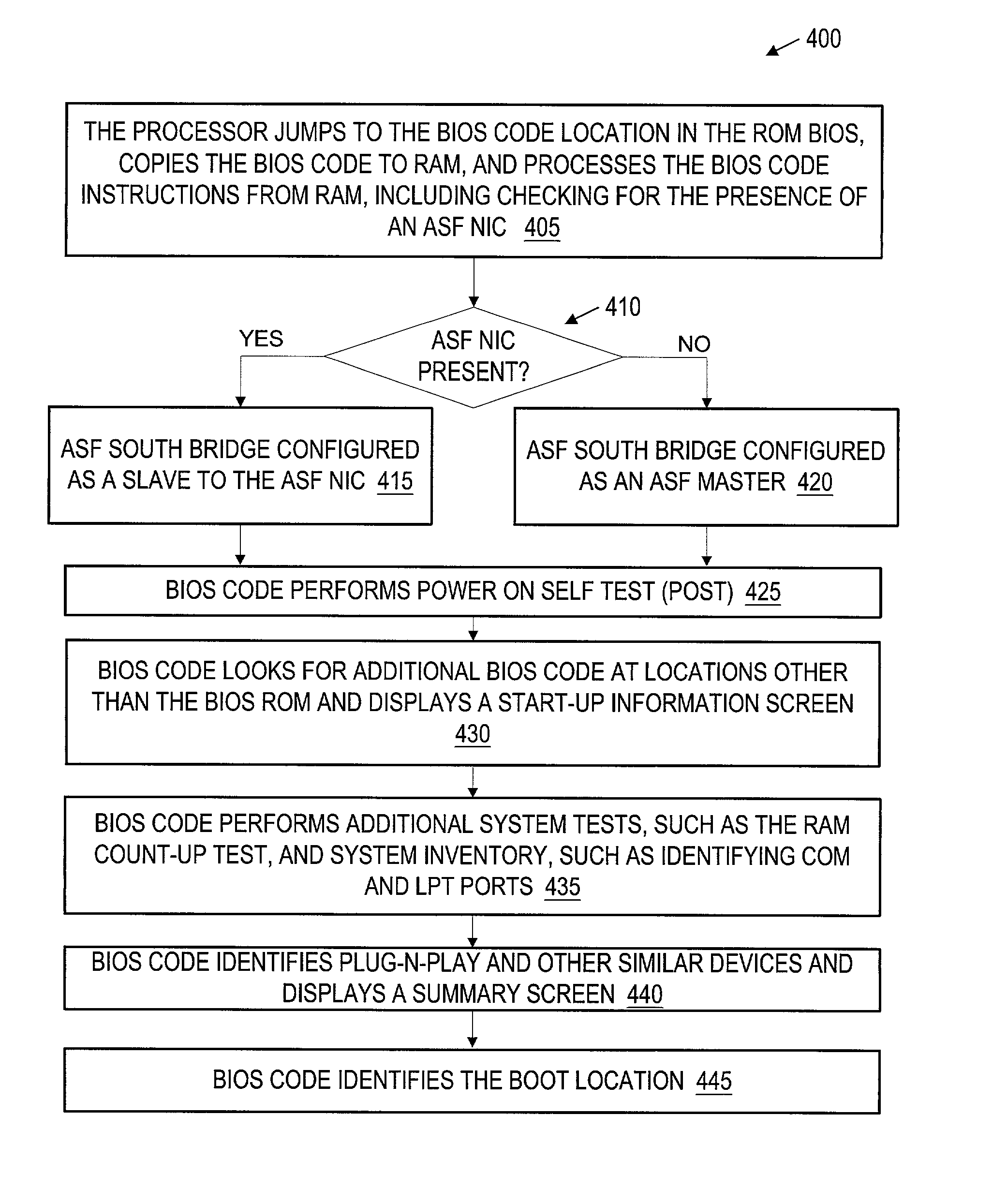
A computer system 100 with a long boot time slows productivity and, at a minimum, irritates users.

Method used


Image

  • Hardware interlock mechanism using a watchdog timer
  • Hardware interlock mechanism using a watchdog timer
  • Hardware interlock mechanism using a watchdog timer

Examples


Embodiment Construction

[0040] Illustrative embodiments of the invention are described below. In the interest of clarity, not all features of an actual implementation are described in this specification. It will, of course, be appreciated that in the development of any such actual embodiment, numerous implementation-specific decisions must be made to achieve the developers' specific goals, such as compliance with system-related and business-related constraints, which will vary from one implementation to another. Moreover, it will be appreciated that such a development effort might be complex and time-consuming, but would nevertheless be a routine undertaking for those of ordinary skill in the art having the benefit of this disclosure. The use of a letter in association with a reference number is intended to show alternative embodiments or examples of the item to which the reference number is connected.

[0041] The following co-pending U.S. Patent Applications are hereby incorporated by reference in their ent...


PUM


Abstract

An integrated circuit, a computer system and a method of operating an computer system are disclosed. The method includes receiving a request for an authentication, at a microcontroller and requesting security data from a security device. The method also includes receiving the security data from the security device, at the microcontroller and evaluating the security data. The method also includes approving the authentication if the security data is evaluated as acceptable.

Description

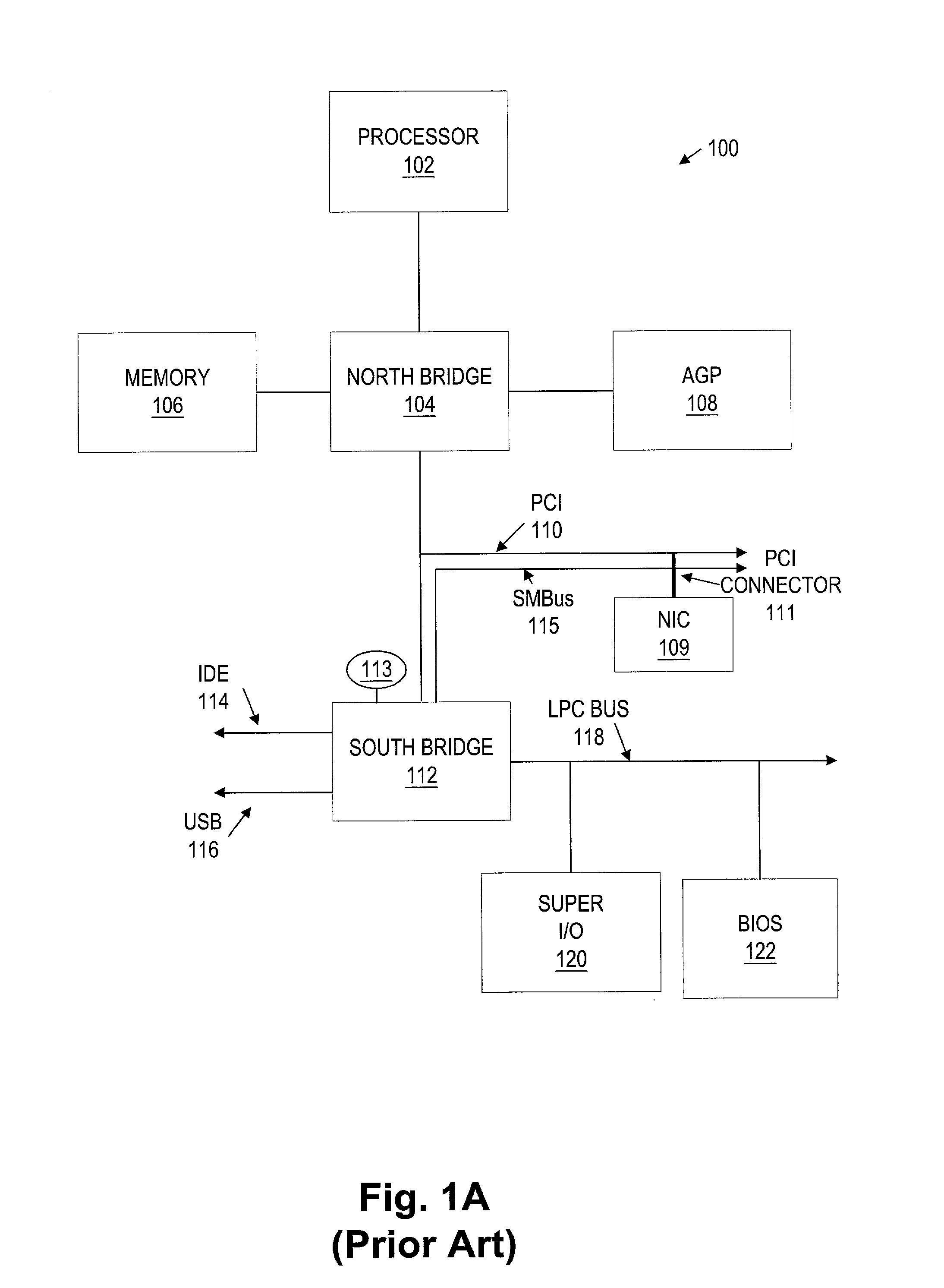
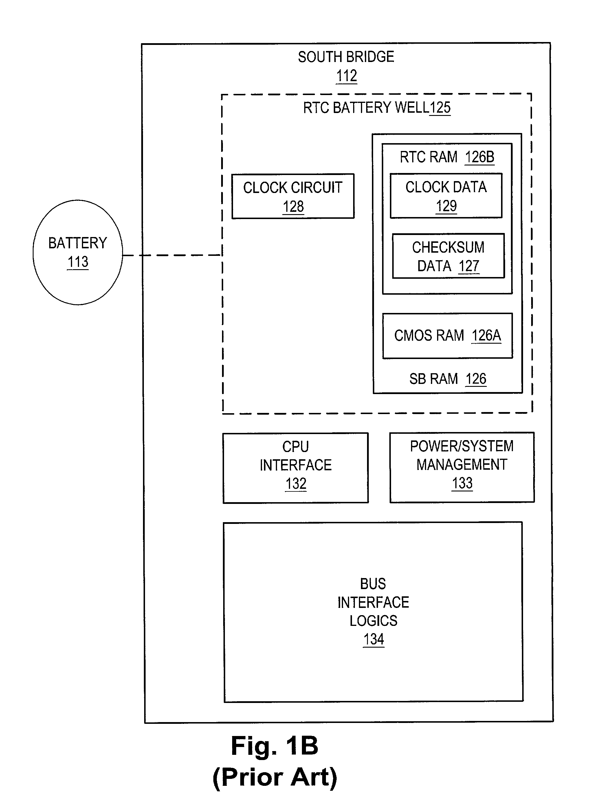
PRIORITY DATA[0001] This application is a continuation-in-part of U.S. patent application Ser. No. 10 / 045,117, filed on Nov. 1, 2001, entitled, "MICROCOMPUTER BRIDGE FOR REMOTE MANAGEABILITY," and whose inventor is Dale E. Gulick.[0002] 1. Field of the Invention[0003] This invention relates generally to computing systems, and, more particularly, to a system and method for preventing unwanted system state changes using a watchdog timer, such as in a personal computer system.[0004] 2. Description of the Related Art[0005] FIG. 1A illustrates an exemplary computer system 100. The computer system 100 includes a processor 102, a north bridge 104, memory 106, Advanced Graphics Port (AGP) device 108, a network interface card (NIC) 109, a Peripheral Component Interconnect (PCI) bus 110, a PCI connector 111, a south bridge 112, a battery 113, an AT Attachment (ATA) interface 114 (more commonly known as an Integrated Drive Electronics (IDE) interface), an SMBus 115, a universal serial bus (USB...

Claims


Application Information

Patent Timeline
Patent Type & Authority Applications(United States)
IPC IPC(8): G06F13/36G06F1/00G06F21/00G06F21/20
CPCG06F2221/2153G06F21/575G06F1/00
Inventor GULICK, DALE E.
Owner GLOBALFOUNDRIES INC
Learn More