
Composite bicycle rim with seamless braking surface

Inactive Publication Date: 2003-06-12
COMPOSITECH
View PDF5 Cites 78 Cited by
  • Summary
  • Abstract
  • Description
  • Claims
  • Application Information

AI Technical Summary

Benefits of technology

[0015] One feature of the present invention is that it provides a light-weight FRP based wheel rim that includes a metal tire receiving ring, having first and second continuous braking surfaces. This feature has the advantage of providing a more reliable, smoother braking surface than was achievable with prior known bicycle rims. As discussed above, the known prior art rim of this type had a slight gap between the first and second ends of the tire receiving ring, when the tire receiving ring was joined to the FRP rim body. Although the ends of the tire receiving ring were joined in a manner that placed the ends of the braking surface in an adjacent, planar relationship, the stresses imposed on the braking surface had the potential to increase the gap between the ends of the tire receiving ring, and had the potential to cause the surfaces to lose their planarity at the juncture between the first and second ends. This erosion of the planarity at juncture between the braking surfaces tended to result in decreased braking performances, and had the potential to decrease the useful life of the product. Useful life could be decreased by the increased gap making it more likely that the brake pad would become snagged or "catch" upon an edge of the braking surface, thereby widening the gap between the two ends of the braking surface.
[0016] The method of producing a rim of the present invention, and the rim produced thereby overcomes this problem by creating a strong metallic bond between the first and second ends of the tire ring at the braking surface, which bond can be machined so that the tire ring is effectively continuous, having no discontinuities between the first and second ends of the tire receiving ring. This continuous surface will likely result in a longer lasting rim having a reduced likelihood of premature degradation in its performance characteristics.
[0018] This feature has the advantage of creating its own bond between the FRP body and the ring, to help better ensure that they maintain their structural integrity. Additionally, the heat and pressure applied in the mold, and the adjacent relationship of the FRP body tire receiving ring within the mold helps to better fit and mechanically bond the FRP body portion of the rim to the ring, to also thereby reduce the likelihood that the ring will become separated from the FRP body.

Problems solved by technology

Although full composite wheels represent the current state-of-the-art in high-tech bicycle rims because of their strength, their light-weight and their aerodynamically efficient profiles, bicycle rims made entirely of FRP composites are not well suited to all uses.
In particular, one difficulty with known full composite bicycle rims, is that it is difficult to form a full FRP composite fiber rim that will accept standard beaded bicycle tires.
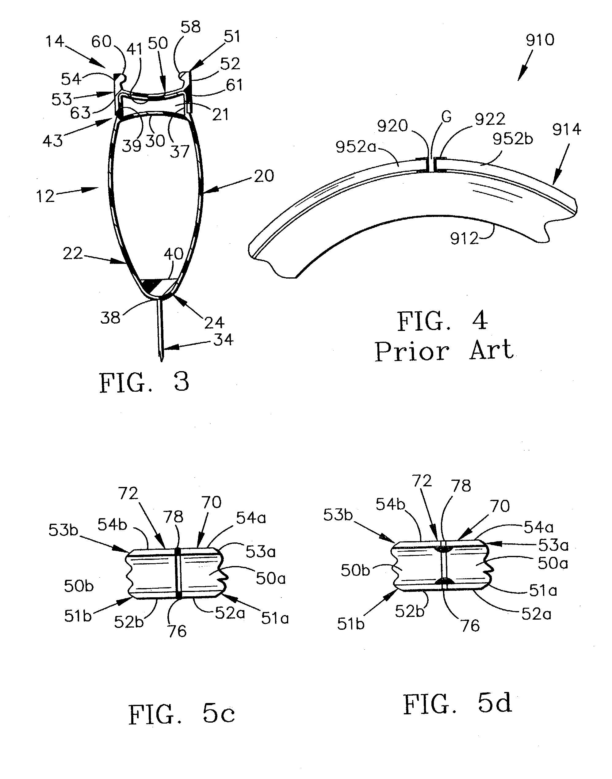
This method of manufacturing the hoop has the disadvantage of leaving a slight gap in the hoop where the first and second ends of the hoop are joined together.
It was found by Applicants that this gap created between the two former ends of the aluminum hoop resulted in a rim that, although having fine performance characteristics, was difficult to manufacture, and which was still subject to improvement in its longevity.

Method used


Image

  • Composite bicycle rim with seamless braking surface
  • Composite bicycle rim with seamless braking surface
  • Composite bicycle rim with seamless braking surface

Examples


Embodiment Construction

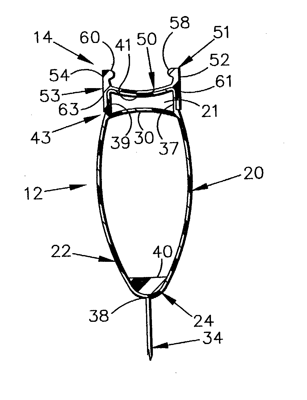
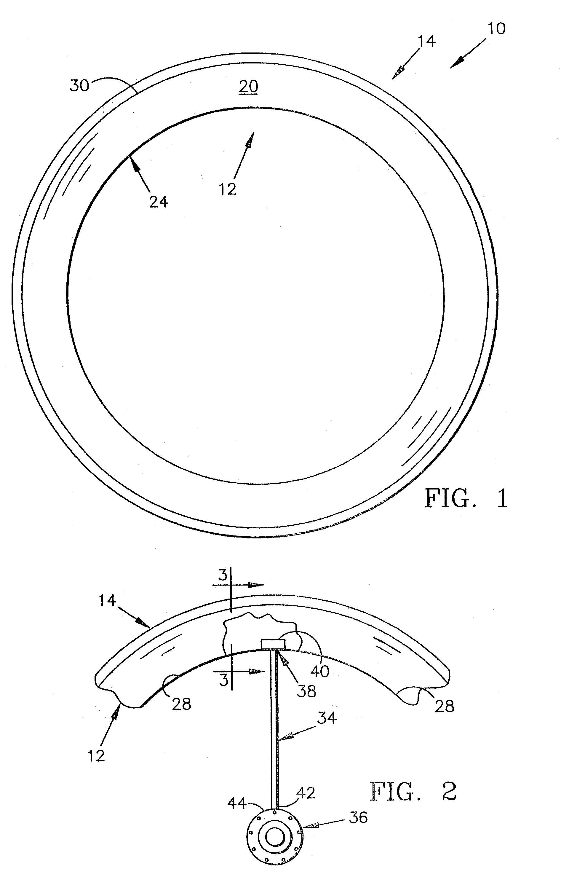
[0029] A fiber reinforced plastic (FRP) based bicycle rim 10 of the present invention is shown in the figures, as being comprised of two primary components, a carbon fiber body 12, that is circumferentially surrounded by an aluminum metal tire receiving ring 14. The tire receiving ring 14 is adapted for receiving the beads of a conventional tire, such as is disclosed in more detail in Sargent U.S. Pat. No. 6,975,645, the disclosure of which is incorporated by reference herein. As best shown in FIG. 3, the FRP body 12 includes a first bulbous side wall portion 20, and a second bulbous side wall portion 22 which is formed as a mirror image of the first bulbous side wall portion 20. The side wall portions 20, 24 have a significant radially extent in order to provide desirable aerodynamic properties to the rim. A cross member 30 extends between the two side walls 20, 22 and defines a cavity 21 into which a foam is placed. The foam, which fills cavity 21, serves as a core over which shee...


PUM

PropertyMeasurementUnit
Pressureaaaaaaaaaa
Heataaaaaaaaaa

Abstract

A fiber resin plastic (FRP) based bicycle rim includes an FRP body and a metal tire receiving ring. The FRP body has first and second side surfaces, an annular outer edge surface, and an annular inner edge surface. The annular inner edge surface includes at least two spoke receiving ports for receiving and supportively coupling at least two spokes to the FRP body. The metal tire receiving ring is coupled to the FRP body and is disposed radially outwardly of the FRP body. The tire receiving ring includes first and second, generally parallel continuous braking surfaces.

Description

I. PRIORITY CLAIM[0001] The instant application claims priority to Ording and Poertner, U.S. Provisional Patent Application No. 60 / 334,220 filed Nov. 28, 2001.II. TECHNICAL FIELD OF THE INVENTION[0002] The present invention relates to rims for bicycle wheels, and more particularly, fiber-reinforced plastic based bicycle wheels rims, and most particularly carbon fiber-based bicycle wheel rims.III. BACKGROUND OF THE INVENTION[0003] Bicycle wheels and rims therefor have been in use for well over a century. Heretofore, most bicycle rims have been made of steel or aluminum. However, in the past few decades, some bicycle rim manufacturers have begun to produce bicycle rims from other materials, such as fiber reinforced plastics (FRPs), including carbon fiber, fiberglass, and nylon fibers, that are mixed in a resin such as epoxy-based resins, phenolic-based resins and / or ester-based resins. Of these composite rims, some have been comprised entirely of FRP composite materials ("full composi...

Claims


Application Information

Patent Timeline
IPC IPC(8): B60B5/02B60B21/06B60B21/08
CPCB60B5/02B60B21/025B60B21/04Y10T29/49524B60B21/08B60B25/00B60B21/062
Inventor ORDING, ANDREWPOERTNER, JOSHUA R.
Owner COMPOSITECH
Learn More