Gravure coating apparatus

Inactive Publication Date: 2003-07-03
FUJIFILM CORP +1
View PDF0 Cites 11 Cited by
  • Summary
  • Abstract
  • Description
  • Claims
  • Application Information

AI Technical Summary

Problems solved by technology

When the doctor blade is used, however, the coating liquid forms a thin film at a coating point at which the gravure roll comes into contact with a backup roll via the web, so that a coating liquid surface in a cell of the gravure roll is liable to become of a concave shape.
This presents a drawback in that the coating film applied to the web sometimes becomes irregular.
As shown in a schematic view of FIG. 4, this liquid return forms a streak-shaped flow depending on the physical properties of the coating liquid 2 and coating speed, which poses a problem in that a streak trouble is caused on the coating surface on the web 4 due to the liquid return.
As a result, when the web 4 is pressed on the gravure roll 3 by the backup roll 6, a force applied to the coating liquid 2 becomes nonuniform, so that unevenness of film thickness is caused on the web 4, causing the streak trouble.
Ho

Method used


Image

  • Gravure coating apparatus
  • Gravure coating apparatus
  • Gravure coating apparatus

Examples


Embodiment Construction

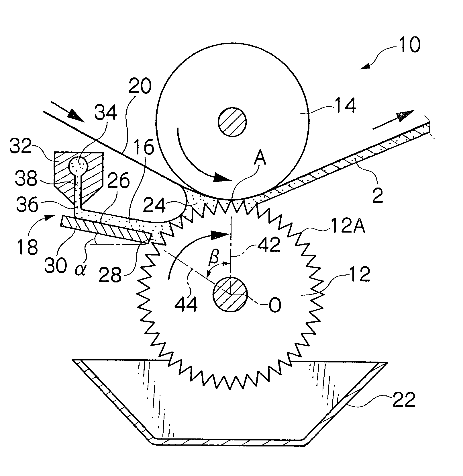
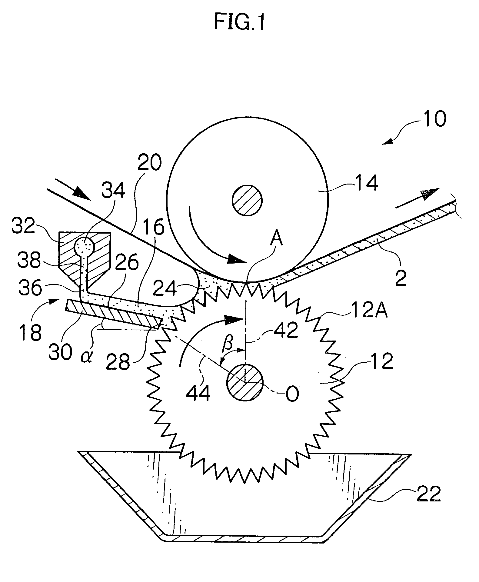
[0031] By using a web of polyethylene terephthalate (PET) of 0.1 mm thick and 1000 mm wide, coating performance of the gravure coating apparatus in accordance with the present invention shown in FIG. 1 (embodiment), the conventional gravure coating apparatus shown in FIG. 3 (comparative example 1), and the conventional gravure coating apparatus disclosed in Japanese Patent Application Publication No. 63-194766 (comparative example 2) was evaluated under the coating conditions given in Table 1.

1 TABLE 1 Coating Amount speed of coating Surface tension Viscosity Coating condition 10 m / min 4 cc / m.sup.2 27 mN / m 2 mPa .multidot. s

[0032] In the test, the coating length of one time on the web was set at 100 m, and the number of streak troubles occurring in a plane shape was counted by sampling 10 m of the coating end portion. The level of occurring streak trouble was evaluated by three grades of A, B and F. A designates a streak trouble within the allowable range of product, which cannot be...


PUM

PropertyMeasurementUnit
Angleaaaaaaaaaa
Angleaaaaaaaaaa
Flexibilityaaaaaaaaaa

Abstract

In the gravure coating apparatus, while a bead portion of a coating liquid is formed between a roll surface of a gravure roll to which the coating liquid is excessively supplied and a web that runs continuously, the web is pressed on the gravure roll by using a backup roll, whereby a desired amount of the coating liquid is applied to the web, a liquid supply device having an inclined surface that is inclined downward toward the roll surface and a gap too narrow for the coating liquid to flow down between the roll surface and the inclined surface is provided at a position near the bead portion on the upstream side in the direction of rotation of the gravure roll so that the coating liquid flows down on the inclined surface and is supplied to the gravure roll. A liquid return of an excess coating liquid that is not used for coating in the bead portion is less liable to occur, so that a streak trouble on a coating surface formed on the web can be prevented from occurring.

Description

[0001] 1. Field of the Invention[0002] The present invention relates to a gravure coating apparatus, and more particularly to a gravure coating apparatus for applying a coating liquid to a flexible substrate (hereinafter referred to as a "web") which runs continuously, the gravure coating apparatus being of a type such that no doctor blade is used.[0003] 2. Description of the Related Art[0004] One of coating apparatuses for applying a coating liquid to a continuously running web is a gravure coating apparatus. In gravure coating, an excess amount of coating liquid supplied to a gravure roll so as to exceed a desired amount of coating liquid is usually scraped off by a doctor blade. When the doctor blade is used, however, the coating liquid forms a thin film at a coating point at which the gravure roll comes into contact with a backup roll via the web, so that a coating liquid surface in a cell of the gravure roll is liable to become of a concave shape. This presents a drawback in th...

Claims


Application Information

Patent Timeline
IPC IPC(8): B05C1/08B05C5/00
CPCB05C1/0808Y10S118/04B05C5/007B05C1/0813
Inventor KODOU, ATSUSHIENDO, SHUUICHIHIROSE, MATSUTAROSANO, DAISUKE
Owner FUJIFILM CORP
Why Eureka
Try Eureka