
Eureka
For R&D, Eureka makes reading and utilizing patents & technical documents easy.
Eureka AIR
Designed for self-driven R&D workflows. Generate viable solutions, solve complex R&D challenges, empower your innovation with AI.

Eureka Materials
Designed for material experts only. Revolutionize your material R&D, from search, analyze, to developing new materials.

TechResearch
Generate reliable direction feasibility study reports for your R&D in just a few steps.

TechSeek
Discover and master advanced knowledge NOW. Basics, ideas, possibilities, all at once.

TechMind
As an expert in R&D Theories, TechMind can generates customized viable solutions instantly.

TechRisk
Analyze your overall solution with one click, know your potential R&D risks in advance.

TechMonitor
Get weekly tech updates, stay abreast of the latest tech innovations and key insights.
Vehicle headlamp
- Summary
- Abstract
- Description
- Claims
- Application Information
AI Technical Summary
Benefits of technology
Problems solved by technology
Method used
Image

Examples
first embodiment
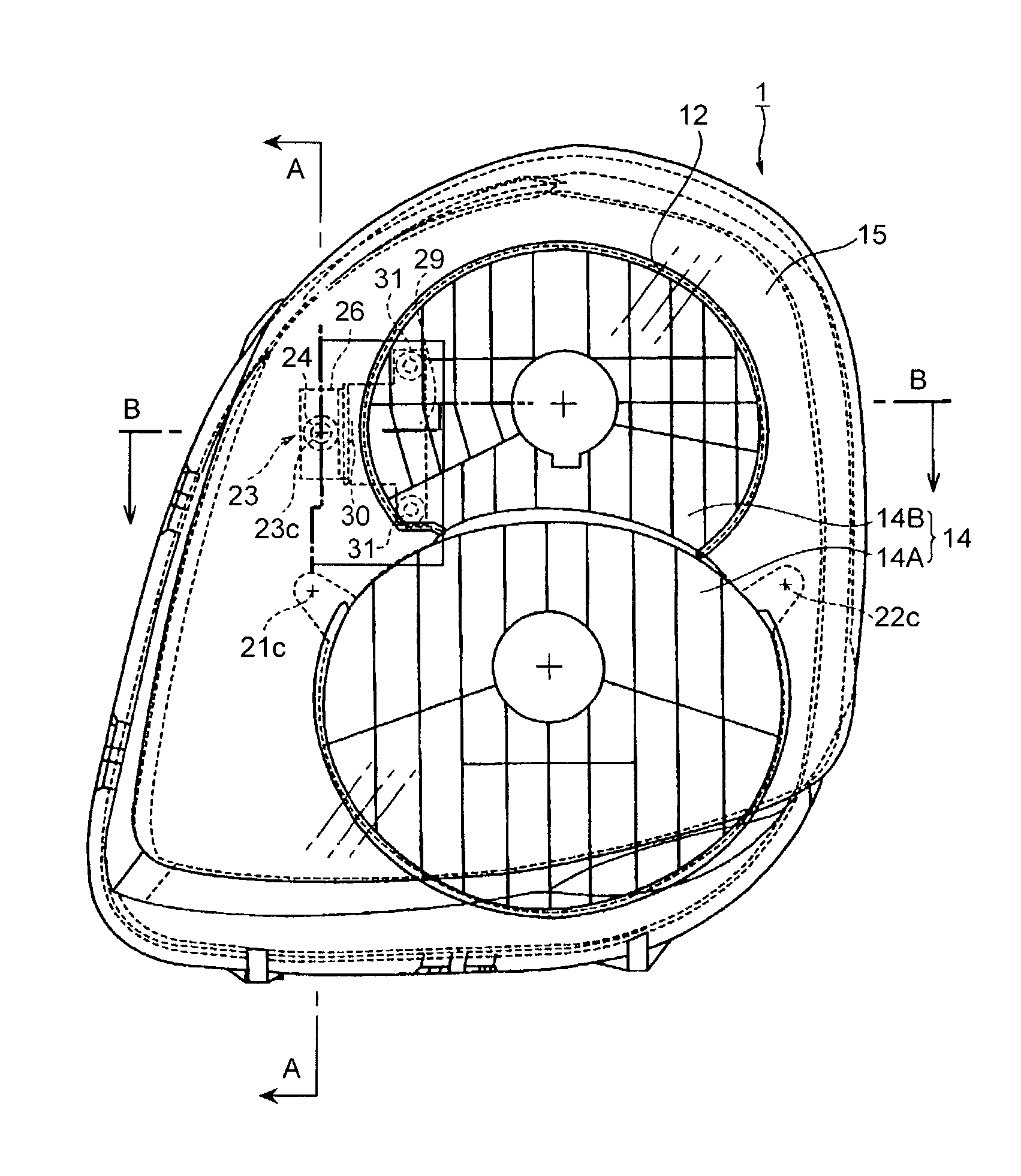
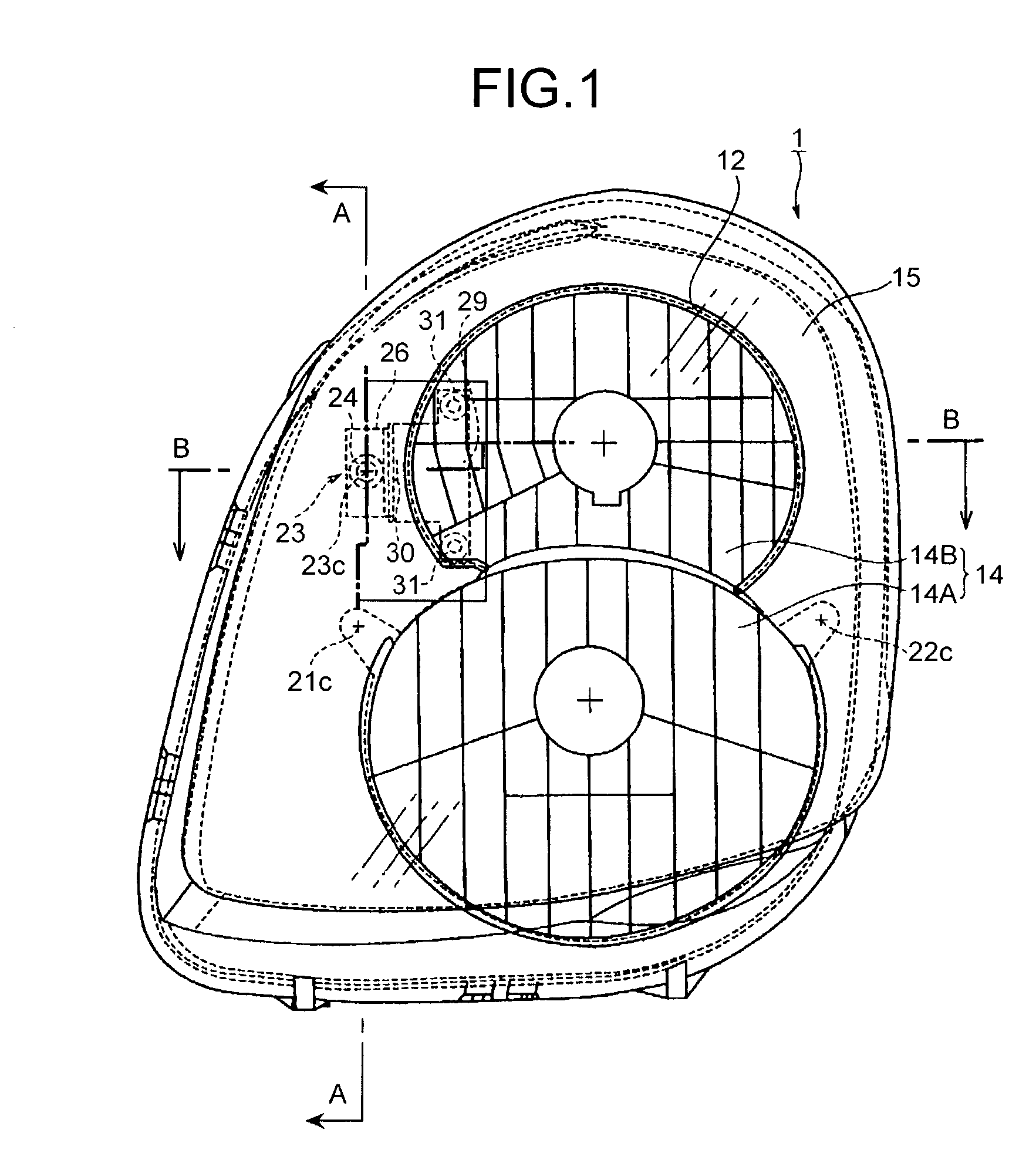
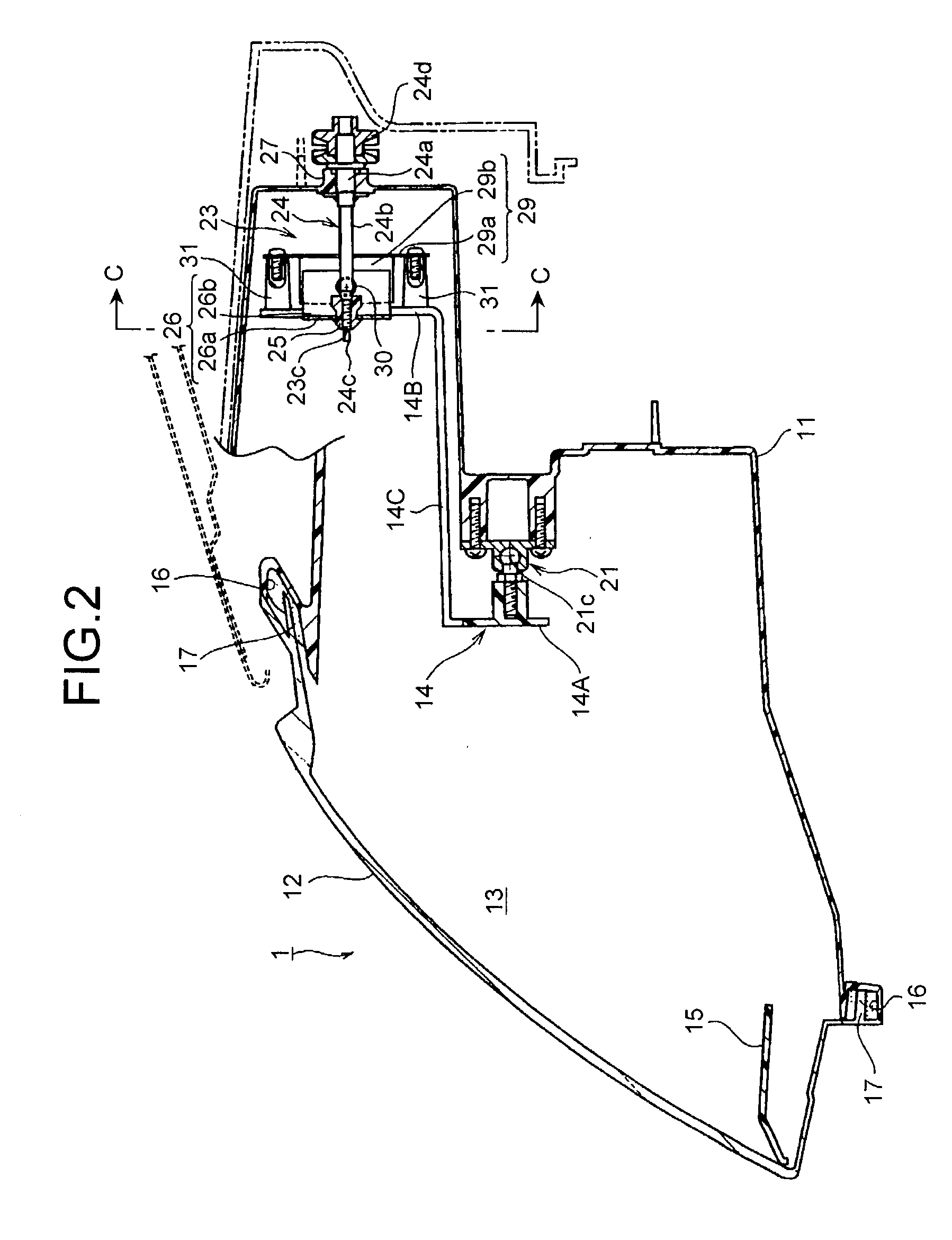
[0028] FIGS. 1 to 7 show a vehicle headlamp 1 according to the present invention. The vehicle headlamp 1 is a quad headlamp, and comprises a housing 11 and a front lens 12 forming a lamp chamber 13 between the housing 11 and the front lens, a reflector 14 provided in the lamp chamber 13, and an inner panel 15 that hides the end portions of the housing 11 and the reflector 14 and the gap between them.
[0029] The housing 11 is fixed to the vehicle frame, via a mounting flange (not shown). A fitting groove 16 is provided on the rim of an opening on the front face of the housing 11.
[0030] The front lens 12 is formed of a transparent lens. A leg portion 17 extending rearwards is provided on the rim of the front lens 12. The leg portion 17 is inserted in and fixed to the fitting groove 16 on the housing 11, to form the lamp chamber 13 between the housing 11 and the front lens 12. As shown in FIG. 1, the headlamp 1 is oblong, in view of the design. Therefore, the front lens 12 is a slant ty...
second embodiment
[0048] FIGS. 8 to 10 show a vehicle headlamp 2 according to the present invention. In the figures, the same reference symbols as in FIGS. 1 to 7 denote the same elements.
[0049] In the vehicle headlamp 2 according to the second embodiment, a transmission member 33 is swingably connected to the nut member 25 and the reflector 14 via a bracket 34.
[0050] The transmission member 33 comprises a flat mounting portion 33a crossing the aiming screw 24, a flat connecting portion 33c substantially parallel to the aiming screw 24, and a dome-shaped sliding portion 33b. A hole 33d is provided in the mounting portion 33a. The hole 33d is formed in an elliptical shape, short in the lateral direction and long in the vertical direction, as in the hole 26c of the transmission member 26 in the first embodiment, so that the transmission member 33 can swing in the direction of a transfer error (in the vertical direction) between the rotation motion of the reflector 14 and the linear motion of the nut me...
third embodiment
[0058] FIGS. 11 to 13 show a vehicle headlamp 3 according to the present invention. In the figures, the same reference symbols as in FIGS. 1 to 10 denote the same elements.
[0059] In the vehicle headlamp 3, a transmission member 42 is swingably connected to the nut member 25 and the reflector 14 via a bracket 40.
[0060] The transmission member 42 comprises a flat first mounting portion 42a and a flat second mounting portion 42b, respectively crossing the aiming screw 24, and a connecting portion 42c substantially parallel to the aiming screw 24. The first mounting portion 42a is provided with a hole 42d. The hole 42d is formed, as in the hole 26c of the transmission member 26 in the first embodiment, and the hole 33d of the transmission portion 33 in the second embodiment, in an elliptical shape, short in the lateral direction and long in the vertical direction (see FIG. 6), so that the transmission member 42 can swing in the direction of a transfer error (in the vertical direction) b...
PUM
 Abstract
Description
Claims
Application Information
 - R&D Engineer
- R&D Manager
- IP Professional
- Industry Leading Data Capabilities
- Powerful AI technology
- Patent DNA Extraction
Browse by: Latest US Patents, China's latest patents, Technical Efficacy Thesaurus, Application Domain, Technology Topic, Popular Technical Reports.
© 2024 PatSnap. All rights reserved.Legal|Privacy policy|Modern Slavery Act Transparency Statement|Sitemap|About US| Contact US: help@patsnap.com