Optical position sensing for well control tools

a technology of optical position sensing and well control, which is applied in the direction of optical radiation measurement, survey, borehole/well accessories, etc., can solve the problem of difficult to determine the operation and performance of individual downhole tools from surface measurements alon

Inactive Publication Date: 2003-07-10
BAKER HUGHES INC
View PDF27 Cites 69 Cited by
  • Summary
  • Abstract
  • Description
  • Claims
  • Application Information

AI Technical Summary

Problems solved by technology

The control of oil and gas production wells constitutes an on-going concern of the petroleum industry due, in part, to the enormous monetary expense involved as well as the risks associated with environmental and safety issues.
With multiple production zones intermingled in the single well bore, it is difficult to determine the operation and performance of individual downhole tools from surface measurements alone.

Method used


Image

  • Optical position sensing for well control tools
  • Optical position sensing for well control tools
  • Optical position sensing for well control tools

Examples


Embodiment Construction

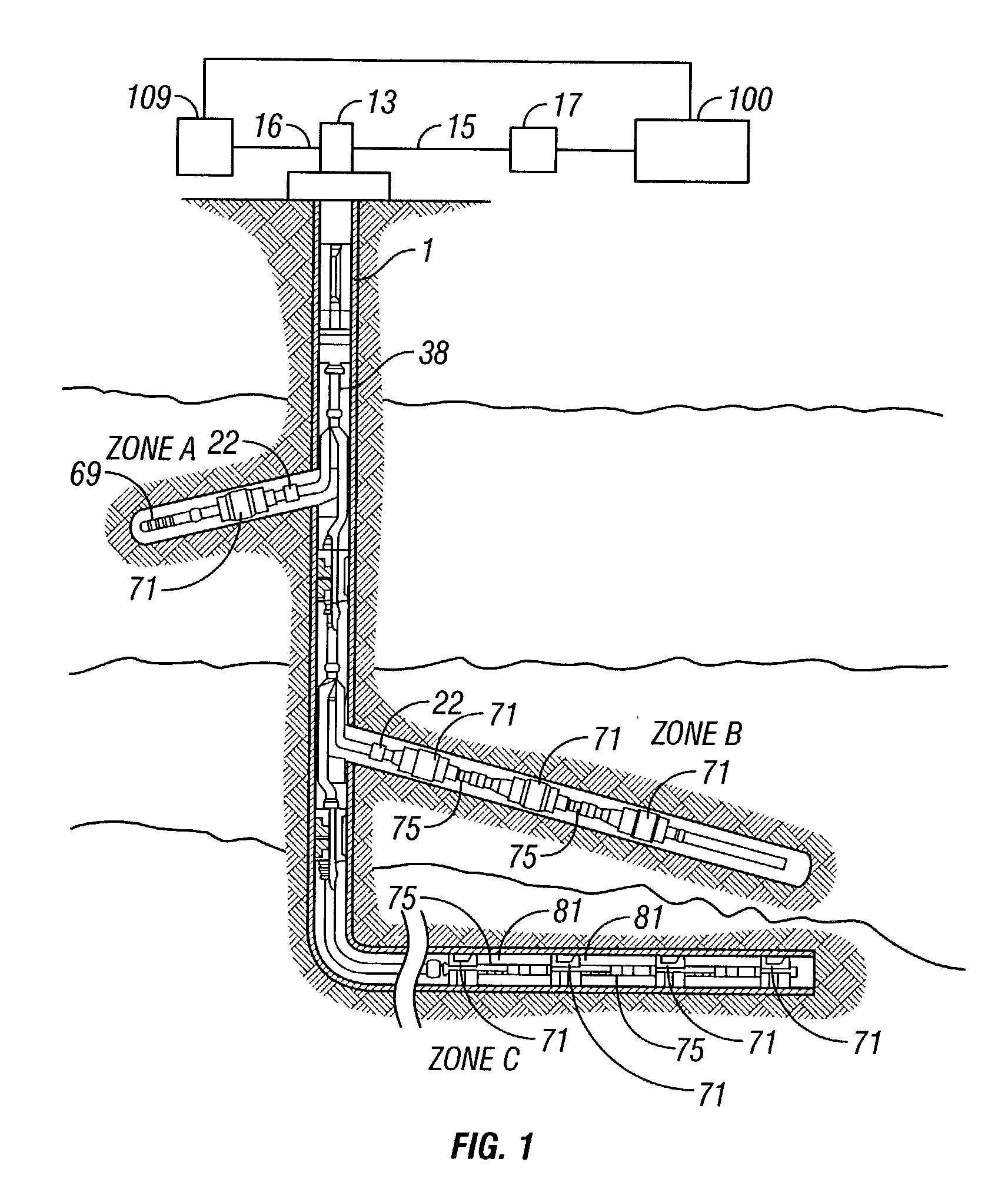
[0029] As is known, a given well may be divided into a plurality of separate zones which are required to isolate specific areas of a well for purposes of producing selected fluids, preventing blowouts and preventing water intake. A particularly significant contemporary feature of well production is the drilling and completion of lateral or branch wells which extend from a particular primary wellbore. These lateral or branch wells can be completed such that each lateral well constitutes a separable zone and can be isolated for selected production.

[0030] With reference to FIG. 1, well 1 includes three zones, namely zone A, zone B and zone C. Each of zones A, B and C have been completed in a known manner.

[0031] In zone A, a slotted liner completion is shown at 69 associated with a packer 71. In zone B, an open hole completion is shown with a series of packers 71 and sliding sleeve 75, also called a sliding sleeve valve. In zone C, a cased hole completion is shown again with the series ...


PUM


Abstract

An apparatus and methods are disclosed for using optical sensors to determine the position of a movable flow control element in a well control tool. A housing has a movable element disposed within such that the element movement controls the flow through the tool. An optical sensing system senses the movement of the element. Optical sensors are employed that use Bragg grating reflections, time domain reflectometry, and line scanning techniques to determine the element position. A surface or downhole processor is used to interpret the sensor signals.

Description

[0001] This application claims the priority of U.S. Provisional Application No. 60 / 332,478 filed on Nov. 14, 2001.[0002] 1. Field of the Invention[0003] This invention relates generally to a method for the control of oil and gas production wells. More particularly, it relates to an optical position sensor system for determining the position of movable elements in well production equipment.[0004] 2. Description of the Related Art[0005] The control of oil and gas production wells constitutes an on-going concern of the petroleum industry due, in part, to the enormous monetary expense involved as well as the risks associated with environmental and safety issues.[0006] Production well control has become particularly important and more complex in view of the industry wide recognition that wells having multiple branches (i.e., multilateral wells) will be increasingly important and commonplace. Such multilateral wells include discrete production zones which produce fluid in either common or...

Claims


Application Information

Patent Timeline
Patent Type & Authority Applications(United States)
IPC IPC(8): E21B34/14E21B43/12E21B47/09E21B47/12
CPCE21B34/14E21B47/123E21B47/09E21B43/12E21B47/135
Inventor BUSSEAR, TERRY R.CARMODY, MICHAEL A.JENNINGS, STEVEN L.HOPMANN, DON A.ZISK, EDWARD J. JR.NORRIS, MICHAEL
Owner BAKER HUGHES INC
Why Eureka
Try Eureka