Remote control system and method for a television receiver

a control system and television receiver technology, applied in the field of remote control, can solve the problems of inconvenient use for users, inability to point and stop at a precise location, and inability to provide functional capabilities of techniques,

Inactive Publication Date: 2003-07-10
KONINKLIJKE PHILIPS ELECTRONICS NV
View PDF0 Cites 73 Cited by
  • Summary
  • Abstract
  • Description
  • Claims
  • Application Information

AI Technical Summary

Benefits of technology

0011] A more complete understanding of the method and apparatus of the present invention is available by reference to the following detailed description when taken in conjunction with the accompanying drawings wherein:

Problems solved by technology

However, the user must get close to the screen and make a personal contact with the screen, which is inconvenient for the user.
However, these techniques do not provide a functional capability that is the same as a mouse and easy to use in conventional computing environments.
Although there have been many attempts to provide the equivalent function of a mouse using a remote control unit, the ability to point and stop at a precise location has been a difficult task.
However, the "gravity effect" on a hand-held device, i.e., a remote control, makes the hand-held device difficult to use, especially for those with unstable hands, to be in a stationary position when pointing it at a monitor screen.

Method used


Image

  • Remote control system and method for a television receiver
  • Remote control system and method for a television receiver
  • Remote control system and method for a television receiver

Examples


Embodiment Construction

[0016] In the following description, for purposes of explanation rather than limitation, specific details are set forth such as the particular architecture, interfaces, techniques, etc., in order to provide a thorough understanding of the present invention. For purposes of simplicity and clarity, detailed descriptions of well-known devices, circuits, and methods are omitted so as not to obscure the description of the present invention with unnecessary detail.

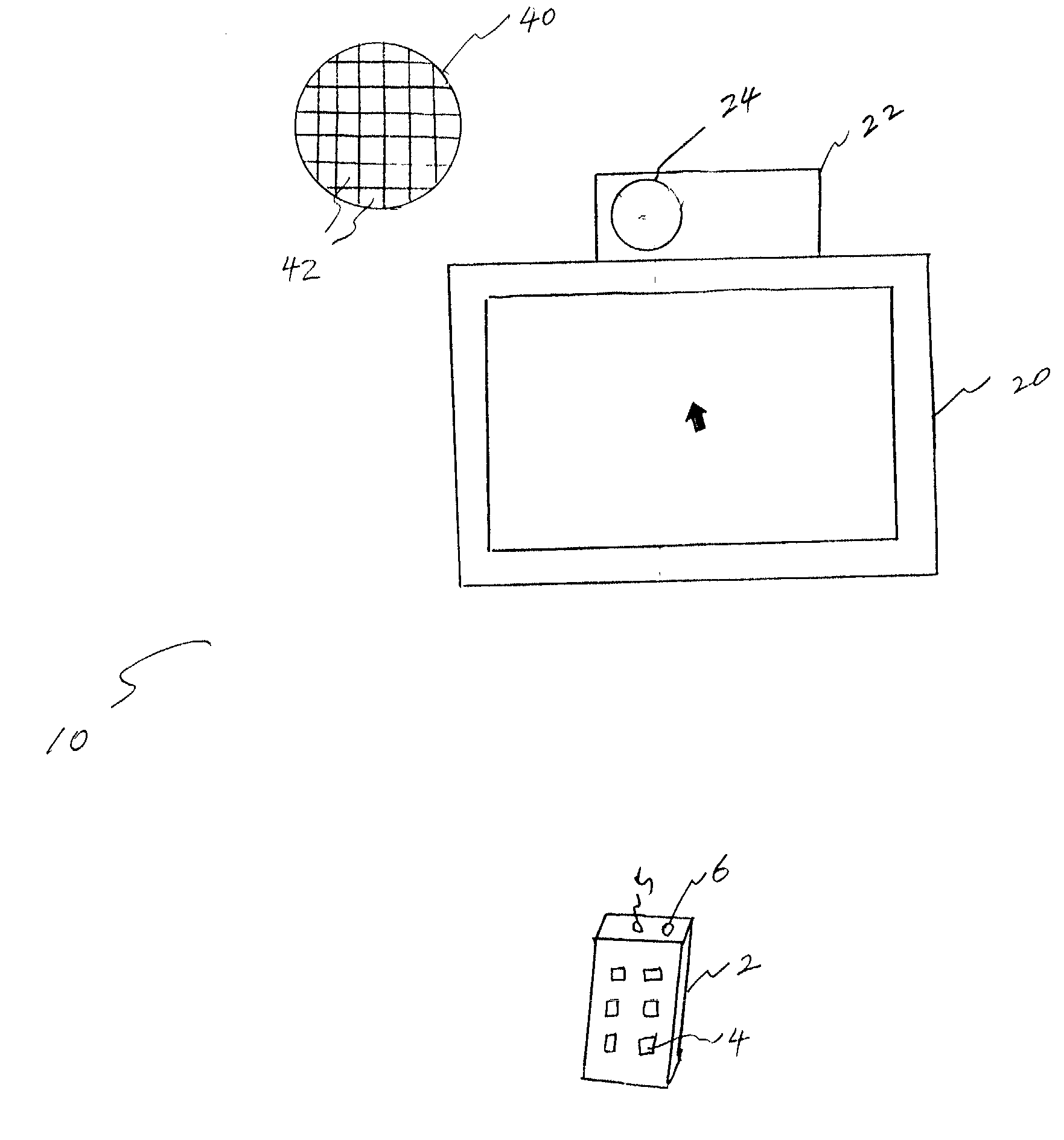
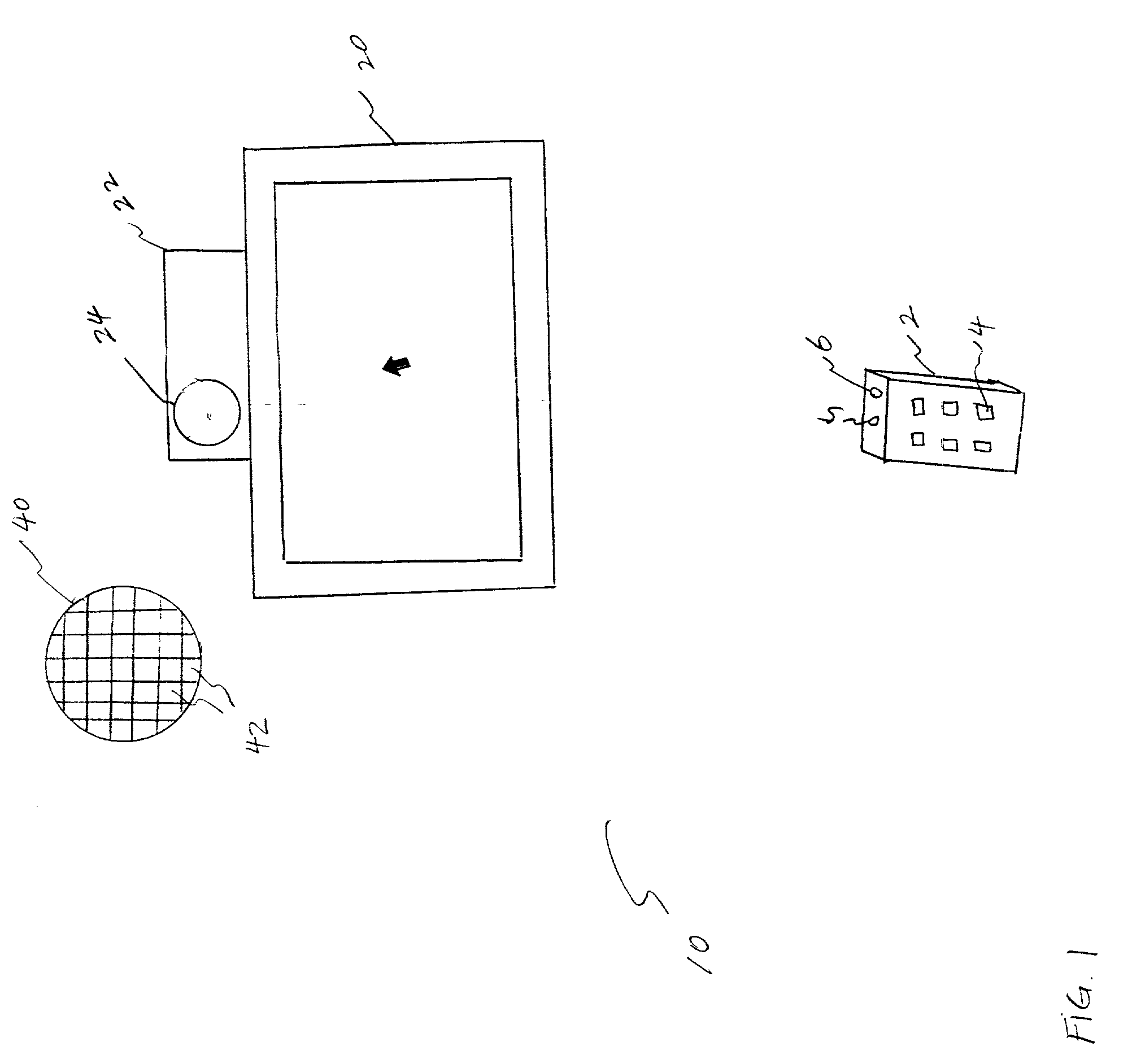
[0017] FIG. 1 is a simplified block diagram illustrating the architecture of a remote control system 10 whereto the embodiments of the present invention are to be applied. The remote control system 10 includes a remote control unit 2 having a plurality of control buttons 4, an infra red (IR) LED 5, and an LED 6; a television (TV) set 20; a control system 22; and, a digital camera 24.

[0018] The front face of the remote control unit 2 may contain an ON / OFF button for activating or terminating the power of the TV set 20 and a numbe...


PUM


Abstract

A system and method for controlling the movement of a cursor on a monitor screen are provided. The system comprising at least one remote control unit having a plurality of push buttons for remotely controlling the moving direction of the cursor on the monitor screen; at least one light emitting element for emitting light that indicates a signal generated by the remote control unit; a light detector for extracting the light movement that is transmitted sequentially from the remote control unit; and, a control unit for displaying the moving position of the cursor on the monitor screen corresponding to the extracted movement of the light from the remote control unit, and also adapted to stop the moving position of the cursor upon releasing the push button of the remote control unit. The movement of the cursor on the monitor screen also can be stopped if the light movement transmitted from the remote control unit changes in the opposite direction.

Description

[0001] 1. Field of the Invention[0002] The present invention relates to a remote hand-held device to be used as a pointing cursor on a display, and more particularly, to a remote control system and method for controlling the movement of a cursor on the display.[0003] 2. Description of the Related Art[0004] With the advent of the Internet technologies, it is foreseeable that the function of computers will be integrated with the television, set-top boxes, or the like. As such, viewers watching television at a certain distance may be able to interact with the television monitor through moving a cursor on the TV screen for screen manipulation. To this end, a touch screen has been proposed to allow a user to select the menus on the TV screen. However, the user must get close to the screen and make a personal contact with the screen, which is inconvenient for the user. Alternatively, viewers may manipulate the upward, downward, left, and right buttons provided in a remote control unit to ...

Claims


Application Information

Patent Timeline
Patent Type & Authority Applications(United States)
IPC IPC(8): G06F3/042H04Q9/00
CPCG06F3/0304G08C2201/32G06F3/0325H04N5/44G06F3/0354
Inventor STRUBBE, HUGO J.
Owner KONINKLIJKE PHILIPS ELECTRONICS NV
Why Eureka
Try Eureka