Secure data storage systems

Inactive Publication Date: 2003-07-10
SHIM YOUNGTACK
10 Cites 53 Cited by

AI-Extracted Technical Summary

Problems solved by technology

Accordingly, most users were not able to cram all of their data into the hard disks of their own computers and were generally compelled to rely on various back-up data storage systems, e.g., storing their data in tens or hundreds of back-up floppy disks or installing external hard disks to the computers and storing extra data therein.
When their computers were stolen or damaged, a major pecuniary damage to such users was to replace their hardwares.
Therefore, it is now virtually impossible to keep a current backup library of hundreds or thousands of floppy disks.
Such a remedy is not amenable at all, however, if the data stored in the lost computer or hard disk driver is highly confidential in nature.
In many cases, a pecun...

Method used

[0068] Exemplary guard member 400 of FIG. 4 may include at least one signal receiving unit 410, at least one degrading unit 420, and/or at least one optional motion unit 430. Signal receiving unit 410 may be arranged to receive the alarm signal that is generated by signal generating unit 330 of access member 300. The alarm signal may then activate degrading unit 420 to effect degradation of at least a portion of the data stored in storage member 210 and/or degradation of at least a portion of storage member 210 itself. In order to facilitate degradation of the data and/or storage member 210 therein, optional motion unit 430 may be arranged to displace, move, translate or rotate at least a portion of storage member 210 (or degrading unit 420) with respect to at least a portion of degrading unit 420 (or storage member 210) before, during, and/or after such degradation. It is appreciated that detailed configuration of the foregoing units of guard member 400 may not necessarily be material within the scope of the invention as long as guard member 400 may operate to perform the foregoing functions. For example, guard member 400 may be arranged to not include any signal receiving unit 410, while degrading unit 420 of guard member 400 may be activated directly by the alarm signal transmitted by signal generating unit 330 of access member 300. By the same token, access member 300 may be arranged not to include any signal generating unit 330, and degrading unit 420 of guard member 400 may be activated directly by logic unit 320 of access member 300.
[0070] FIG. 5 is a perspective view of a prior art hard disk unit according to the present invention. A hard disk unit (i.e., hard disk driver or simply referred to as hard disk) 521 includes at least one data storage device or data storage unit such as a magnetic or optical disk 522, two read/write magnetic or optical heads 523 each being disposed on a top surface 522a and a bottom surface 522b of disk 522, a disk rotator 524 arranged to rotate magnetic or optical disk 522, and a head driver 525 arranged to laterally move read/write heads 523. Magnetic or optical disk 522 typically stores the data therein by forming therealong multiple magnetic or optical bands. Read/write heads 523 may generally contain metal coils that are wound around a metal core made of, e.g., iron, and are disposed adjacent surfaces 522a, 522b of magnetic or optical disk 522. When hard disk unit 521 is to operate in the real mode, read/write heads 523 are disposed adjacent to the magnetic or optical bands formed on surfaces 522a, 522b of magnetic or optical disk 522 rotated by disk rotator 524. The magnetic or optical bands may induce electric current through the coils of read/write heads 523 that are converted into the bit-wise data. When hard disk unit 521 operates in a write mode, an electric current may be fed to the coils of read/write heads 523 according to sequences of the data to be written on magnetic or optical disk 522. The current-flowing coils generate a magnetic field therearound and magnetize one or both surfaces 522a, 522b of magnetic or optical disk 522. During such read/write operations, disk rotator 524 may rotate magnetic or optical disk 522 to facilitate the reading and writing processes. Head driver 525 is arranged to move read/write heads 523 back and forth across top and/or bottom surfaces 522a, 522b of magnetic or optical disk 522 so that read/write heads 523 can access all areas of top and/or bottom surfaces 522a, 522b of magnetic or optical disk 522 that are available for processing such data. Hard disk unit 521 shown in FIG. 5 also includes a pivot 525b and a pair of arms 525a, where arms 525a connect read/write heads 523 to pivot 525b. By properly arranging rotatable pivot 525b, arms 525a and read/write heads 523 can access different areas across magnetic or optical disk 522. Hard disk unit 521 is generally disposed in a case (not shown) to prevent collection of dust. It is noted that the conventional hard disk units having configurations different from the one shown in FIG. 5 may also be used. For example, such a disk unit may include two or more magnetic or optical disks and three or more read/write heads.
[0079] In any of the above magnetic embodiments, at least a portion of storage member 210 may be arranged to move, translate or rotate during the degradation of the portion of storage member 210 or the data stored therein. Such movement, translation, and rotation generally facilitate distribution of the magnetic fluxes onto wider portions of storage member 210 and yield more efficient degradation thereof. For example, various magnetic heads 452, 462 may be attached to auxiliary arms 457, 467 which extend toward rotatable hinges 458, 468 such that such heads 452, 462 may be moved across disk 422 and degrades a substantial portion of the data stored therein. Although not shown in any of the figures, magnetic heads 452, 462 may also be disposed in other locations such as, e.g., adjacent to rotating shafts of disk rotator 524. Magnetic heads 452, 462 may be able to rotate by a centrifugal force generated by rotating disk 522. When multiple disks 522 are stacked along rotating shaft 524, foregoing magnetic heads 452, 462 may be used in any number, any arrangement or any combination. The foregoing per...

Abstract

The present invention relates to various data storage systems and methods therefor capable of allowing an authorized user to process various data stored therein and for preventing an unauthorized user from accessing such data. Such a data storage system may include at least one storage member, at least one process member, and at least one guard member. The storage member may be arranged to store the data therein and the process member may operationally be coupled to the storage member and arranged to process the data stored in the storage member. The guard member may operationally be coupled to the storage member and arranged to effect degradation of at least a portion of such data stored in the storage member and/or degradation of at least a portion of such a storage member itself. As will be described below, various guard members of this invention may effect such degradations in many different ways, e.g., magnetically, optically, chemically, mechanically, and the like. Therefore, the data storage systems and methods therefor of the present invention can provide secure means and methods for protecting data from being accessed by unauthorized users.

Application Domain

Digital data processing detailsUnauthorized memory use protection +2

Technology Topic

Data storage systemComputer security +4

Image

  • Secure data storage systems
  • Secure data storage systems
  • Secure data storage systems

Examples

  • Experimental program(1)

Example

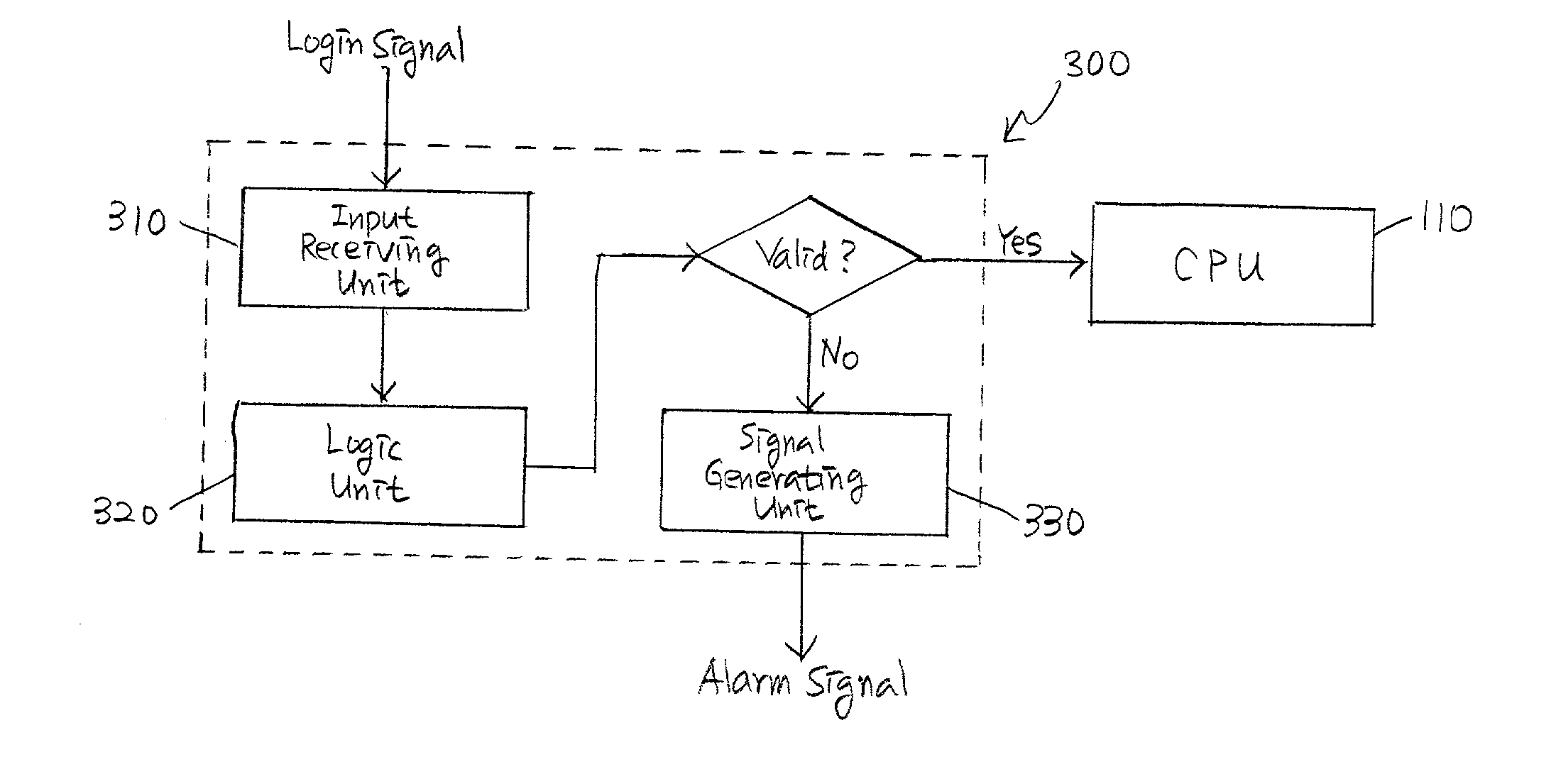
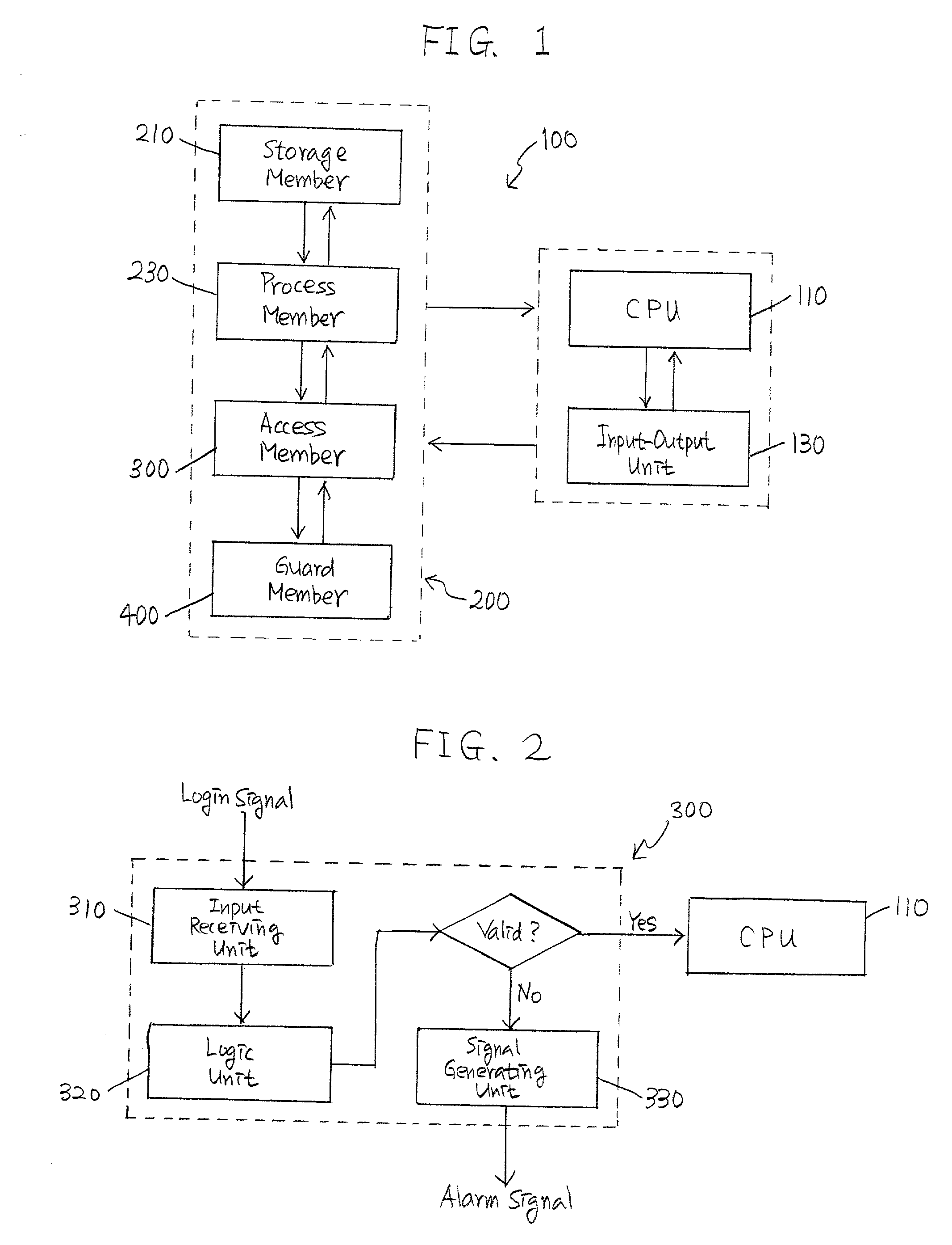
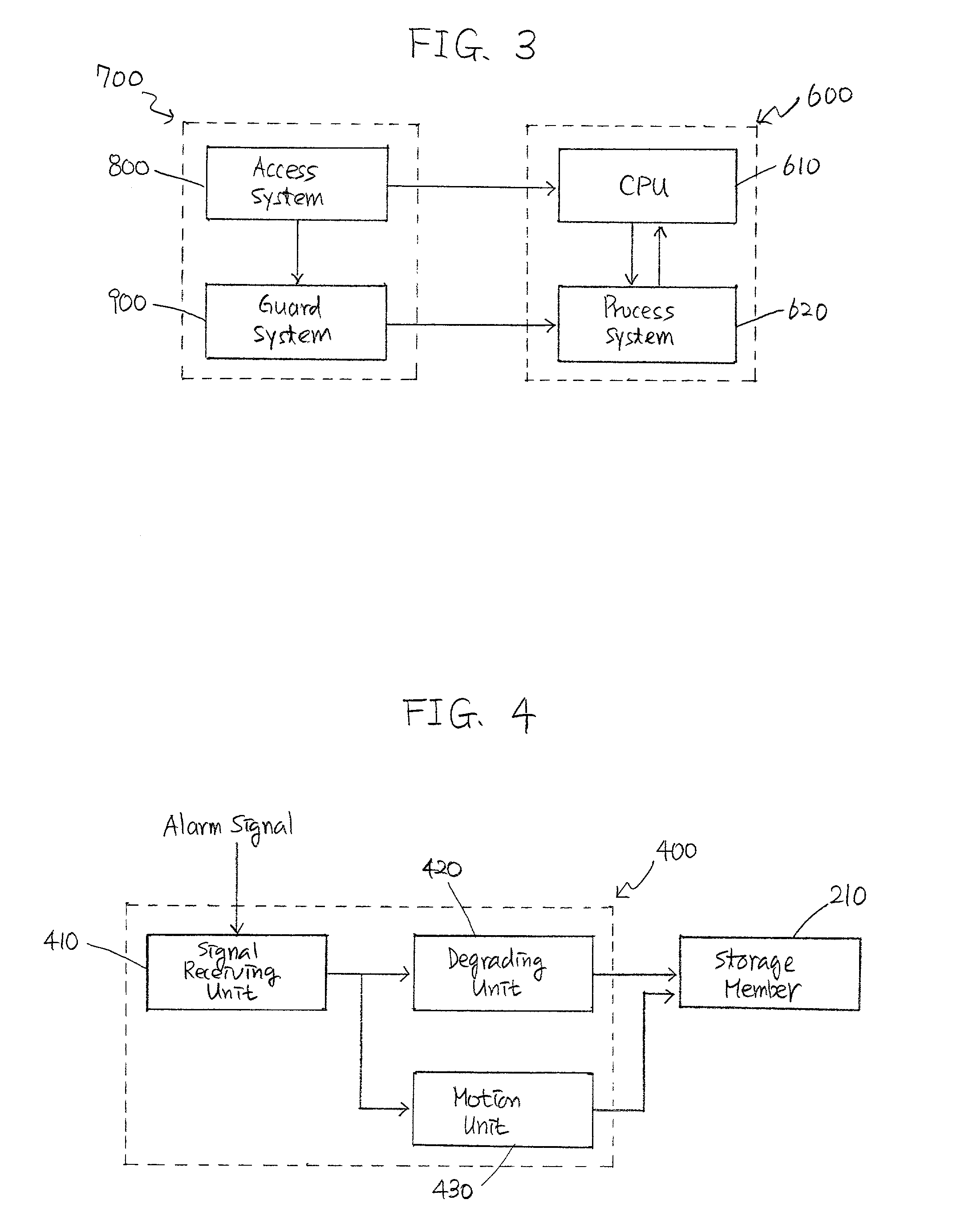
[0057] The present invention relates to various data storage systems and methods therefor capable of allowing an authorized user to process various data stored therein and for preventing an unauthorized user from accessing and processing the data. Following two steps are generally required to fulfill the foregoing objectives of this invention, i.e., detecting unauthorized attempts by the unauthorized user to access such data and degrading at least a portion of the data before the unauthorized user accesses and/or processes the data. Such data storage systems and methods therefor may be readily applied to various data storage devices such as, e.g., hard disks, RAMs, ROMs, and disk drivers for personal as well as main-frame computers and may also be incorporated into floppy disks, compact disks, digital video disks, and/or ZIP disks which can be processed by the foregoing drivers. FIGS. 1 to 7 describe various exemplary embodiments of the data storage systems, their constituents, and methods therefor according to the invention. It is noted, however, that the exemplary embodiments of the systems and methods described herein are only illustrative and not intended to limit the scope of this invention.
[0058] FIG. 1 is a schematic diagram of an exemplary data storage system according to the present invention, where such a data storage system 200 may be incorporated into a computer 100 and used as a hard disk thereof. For ease of illustration, computer 100 in FIG. 1 is simplified as comprising at least one central processing unit (i.e., the "CPU") 110, at least one input-output unit 130, and at least one data storage system 200 which may in turn include at least one storage member 210, at least one process member 230, at least one access member 300, and at least one guard member 400. Storage member 210 of data storage system 200 may be generally arranged to magnetically or optically store various data therein. Process member 230 of data storage system 200 may be arranged to process the data stored in storage member 210, i.e., reading data therefrom and writing data thereonto, as well as to perform other tasks such as, e.g., rearranging such data, formatting storage member 210, and so on. The CPU 110 may run various application programs and/or process such data based on, e.g., external commands received through input-output unit 130. Access member 300 of data storage system 200 may be arranged to receive various login signals such as log-in commands through input-output unit 130 and to assess whether such login signals are "valid login signals" entered by authorized users or whether such login signals are "invalid login signals" entered by unauthorized users. Guard member 400 may be operationally coupled to storage member 210 and arranged to degrade at least a portion of the data stored in storage member 210.
[0059] In operation, data storage system 200 of FIG. 1 may be arranged to prevent the unauthorized user from accessing the data stored in storage member 210 of data storage system 200. For example, an user may enter an login signal through input-output unit 130. Access member 300 receives such a login signal and assesses authenticity thereof. When such a login signal is verified as the valid login signal entered by the authorized user, access member 300 grants the user the access to the data stored in storage member 210. Upon assessing unauthorized attempts to assess the data by the unauthorized user, however, access member 300 alerts guard member 400 which then operates to degrade at least a portion of the data stored in storage member 210.
[0060] Foregoing data storage systems 200 and various members thereof may be realized by various embodiments. For example, storage member 210 may be generally arranged to store data which may be characters, numbers, symbols, texts, voices, sounds, colors, images, and the like. Storage member 210 may be arranged to store such data in any arbitrary format, although various digital formats may be preferred. Storage member 210 may include at least one magnetic unit arranged to use magnetism or magnetic characteristics of at least a portion of storage member 210 to store the data therein or at least one optical unit arranged to use optics or optical characteristics thereof to store the data therein. The magnetic unit may include one or more magnetic disks, magnetic tapes, magnetically operating semiconductor memory chips, and so on, while the optical unit may include at least one optical disk, optically operating semiconductor memory chip, and the like. Storage member 210 may also include at least one floppy disk, hard disk, compact disk, and/or digital video disk, where such a disk may be a read-only disk, a recordable disk, and/or a rewritable disk. Examples of such a storage member 210 may include a random access memory, a flash memory, and a read-only memory.
[0061] Process member 230 may include at least one magnetic head and/or at least one optical head, each of which may process at least a portion of any of the foregoing data. Process member 230 may be arranged to perform reading such data from storage member 210 and/or writing or recording such data into storage member 210.
[0062] FIG. 2 is a schematic diagram of an exemplary embodiment of an access member of the data storage system according to the present invention. Access member 300 may be arranged to detect an unauthorized attempt to access the data by the unauthorized user. Such an unauthorized attempt may include receiving an invalid login signal such as an invalid password or at least one characteristics of the unauthorized user entered by the unauthorized user, unauthorized movement of storage member 210, unauthorized uncoupling of storage member 210 from an article to which access member 300 is coupled, unauthorized disassembly of storage member 210, and the like.
[0063] Particular examples of the unauthorized attempts may include, but not necessarily limited to, receiving the invalid login signals for a pre-determined number of times, receiving the invalid login signal for a pre-determined period, receiving no valid login signals for a pre-selected period, and the like. As discussed above, the invalid login signals relating to the characteristics of the unauthorized user may include visual or audio signals representing, e.g., finger prints, facial patterns, distribution patterns of blood vessels in various anatomical parts including retinas, eyes, hands, and arms, voices, breadths, various physiological characteristics, and the like. Other types of login signals may also be used separately or in conjunction with the foregoing login signals. For example, the user may wear a signaling device transmitting secondary login signals through a wire or wirelessly. Therefore, when the user wears such signaling devices within a pre-selected distance and/or in the proximity of access member 300, access member 300 may receive both the primary login signal and the secondary signal and may assess validity of the user.
[0064] Access member 300 may be arranged to sense or monitor any movement of storage member 210 with respect to stationary objects such as the ground and/or to other parts of data storage system 200 and computer 100 such as CPU 110, input-output unit 130, process member 230, guard member 400, and so on. For this purpose, access member 300 may include at least one conventional motion sensor. Alternatively, access member 300 may be arranged to sense or monitor mechanical, physical, electrical, optical, and/or functional uncoupling of storage member 210 from any articles to which at least a portion of access member 300 may be mechanically, physically, electrically, optically, and/or functionally coupled, respectively. Various conventional sensors may be applied to sense or monitor such uncoupling. For example, a displacement sensor and/or a force transducer may be incorporated between storage member 210 and any of the foregoing articles to monitor physical and/or mechanical uncoupling of storage member 210. Conventional voltmeters or amperometers may be incorporated between storage member 210 and such an article so as to measure electrical coupling and uncoupling therebetween. Depending upon the detailed configuration, the sensors may be arranged to assess the uncoupling as, e.g., an open circuit, a closed circuit, a change in a circuit voltage and/or current, and so on. Similarly, an optical sensor may also be disposed to construct a line of detection and arranged to monitor any object protruding across and/or crossing the line, thereby monitoring optical coupling and/or uncoupling therebetween. When storage member 210 is arranged to have at least one memory unit for storing such data and a housing for retaining at least a substantial portion of the memory unit therein, access member 300 may include any of the foregoing sensors so as to monitor a disassembly of at least a portion of the memory unit from and/or out of the housing.
[0065] Access member 300 may include at least one input receiving unit 310, at least one logic unit 320, and at least one signal generating unit 330. Input receiving unit 310 may be generally arranged to receive a login signal entered by the user through input-output unit 130 and relays the input signal to logic unit 320 which then assesses its validity, e.g., by comparing the login signal of the user with contents of a list or an array of authorized passwords, anatomical and/or physiological characteristics of the authorized users, and so on. When the login signal is assessed to be valid, logic unit 320 may allow the user to access an operating system and data stored in storage member 210. However, when the login signal is assessed to be invalid, logic unit 320 activates signal generating unit 330 which in turn generates an alarm signal and transmits such a signal to guard system 400 that will be discussed in greater detail below.
[0066] It is appreciated that detailed configuration of various members of this invention may not be material within the scope of the invention as long as such members may operate to accomplish such foregoing objectives. For example, a single input-output unit 130 of computer 100 may additionally be used as input receiving unit 310 of access member 300. This embodiment may readily be realized by incorporating suitable software into input-output unit 130. Input receiving unit 310 and logic unit 320 may be combined into a single unit. Alternatively, signal processing unit 330 may be combined with one or both of input receiving unit 310 and logic unit 320. Other functional equivalents may be also employed as long as access member 300 may be arranged to monitor an unauthorized attempt to log in to computer 100 and/or to access the data. For example, FIG. 3 denotes a schematic diagram of another exemplary data storage system with configuration different from that of FIG. 1 according to the present invention. In this embodiment, a computer 600 is represented by two functional units, such as a CPU 610 and a process system 620, both corresponding to CPU 110 and process member 130 of FIG. 1, respectively. Provided with computer 600 is a data security system 700 that includes an access system 800 and a guard system 900, each of which may be at least substantially similar or identical to access member 300 and guard member 400 of FIG. 1, respectively. Although not shown in this figure, process system 620 may include at least one storage member, data read-only member, data write-only member, data read-write member, and so on. Access system 800 may be functionally coupled to CPU 610 and/or process system 620 and arranged to monitor such unauthorized attempts to access the data stored in computer 600 and/or its storage member. Guard system 900 may also be functionally coupled to CPU 610 and/or process system 620, and may be arranged to degrade at least a portion of the data. It is also appreciated that input receiving unit 310 and/or logic unit 320 may be arranged to provide the user more than one opportunity to provide valid login signals. For example, when the user may supply invalid login signals, one of input receiving unit 310 and/or login unit 320 may allow the user to provide one or more login signals. As discussed above, detailed configuration and/or architecture of access member 300 is generally a matter of choice that largely depends upon a design selection made by one of ordinary skill in the relevant art.
[0067] FIG. 4 is a schematic diagram of an exemplary embodiment of a guard member of the data storage system according to the present invention. Guard member 400 may be operationally coupled to at least one of storage member 210 and access member 300. Upon detecting any of the foregoing unauthorized attempts by the unauthorized user or after elapsing a pre-determined period of detecting such attempts, guard member 400 may be arranged to degrade at least a portion of the data stored in storage member 210. Guard member 400 of this invention may be arranged such that a first amount of such data degraded thereby during a pre-determined period is larger than a second amount of such data processed by process member 230 during the same predetermined period. Guard member 400 may preferably be arranged not to encrypt the data and not to perform reading the data from storage member 210 and/or writing the data into storage member 210.
[0068] Exemplary guard member 400 of FIG. 4 may include at least one signal receiving unit 410, at least one degrading unit 420, and/or at least one optional motion unit 430. Signal receiving unit 410 may be arranged to receive the alarm signal that is generated by signal generating unit 330 of access member 300. The alarm signal may then activate degrading unit 420 to effect degradation of at least a portion of the data stored in storage member 210 and/or degradation of at least a portion of storage member 210 itself. In order to facilitate degradation of the data and/or storage member 210 therein, optional motion unit 430 may be arranged to displace, move, translate or rotate at least a portion of storage member 210 (or degrading unit 420) with respect to at least a portion of degrading unit 420 (or storage member 210) before, during, and/or after such degradation. It is appreciated that detailed configuration of the foregoing units of guard member 400 may not necessarily be material within the scope of the invention as long as guard member 400 may operate to perform the foregoing functions. For example, guard member 400 may be arranged to not include any signal receiving unit 410, while degrading unit 420 of guard member 400 may be activated directly by the alarm signal transmitted by signal generating unit 330 of access member 300. By the same token, access member 300 may be arranged not to include any signal generating unit 330, and degrading unit 420 of guard member 400 may be activated directly by logic unit 320 of access member 300.
[0069] Various mechanisms may be incorporated into such degrading unit 420 for such degradations such as, e.g., magnetic degradation of the data, optical degradation of the data, chemical degradation of storage member 210 and/or data, mechanical degradation of storage member 210 and/or data, and the like. In addition, depending upon the nature of such degradation, guard member 400 may include at least one power supply unit arranged to provide guard member 400 with at least one of mechanical, electrical, and/or magnetic power enough to effect the degradation of storage member 210 and/or the data. FIGS. 6 through 8 illustrate different embodiments of degrading unit 420 in greater details. In order to juxtapose structural or configurational differences between conventional disk drive and data storage system 200 of the present invention, a typical conventional disk drive is described in FIG. 5.
[0070] FIG. 5 is a perspective view of a prior art hard disk unit according to the present invention. A hard disk unit (i.e., hard disk driver or simply referred to as hard disk) 521 includes at least one data storage device or data storage unit such as a magnetic or optical disk 522, two read/write magnetic or optical heads 523 each being disposed on a top surface 522a and a bottom surface 522b of disk 522, a disk rotator 524 arranged to rotate magnetic or optical disk 522, and a head driver 525 arranged to laterally move read/write heads 523. Magnetic or optical disk 522 typically stores the data therein by forming therealong multiple magnetic or optical bands. Read/write heads 523 may generally contain metal coils that are wound around a metal core made of, e.g., iron, and are disposed adjacent surfaces 522a, 522b of magnetic or optical disk 522. When hard disk unit 521 is to operate in the real mode, read/write heads 523 are disposed adjacent to the magnetic or optical bands formed on surfaces 522a, 522b of magnetic or optical disk 522 rotated by disk rotator 524. The magnetic or optical bands may induce electric current through the coils of read/write heads 523 that are converted into the bit-wise data. When hard disk unit 521 operates in a write mode, an electric current may be fed to the coils of read/write heads 523 according to sequences of the data to be written on magnetic or optical disk 522. The current-flowing coils generate a magnetic field therearound and magnetize one or both surfaces 522a, 522b of magnetic or optical disk 522. During such read/write operations, disk rotator 524 may rotate magnetic or optical disk 522 to facilitate the reading and writing processes. Head driver 525 is arranged to move read/write heads 523 back and forth across top and/or bottom surfaces 522a, 522b of magnetic or optical disk 522 so that read/write heads 523 can access all areas of top and/or bottom surfaces 522a, 522b of magnetic or optical disk 522 that are available for processing such data. Hard disk unit 521 shown in FIG. 5 also includes a pivot 525b and a pair of arms 525a, where arms 525a connect read/write heads 523 to pivot 525b. By properly arranging rotatable pivot 525b, arms 525a and read/write heads 523 can access different areas across magnetic or optical disk 522. Hard disk unit 521 is generally disposed in a case (not shown) to prevent collection of dust. It is noted that the conventional hard disk units having configurations different from the one shown in FIG. 5 may also be used. For example, such a disk unit may include two or more magnetic or optical disks and three or more read/write heads.
[0071] FIG. 6 is a perspective view of another exemplary embodiment of a guard member of the data storage system effecting magnetic degradation of a storage member and/or various data according to the present invention. Such a guard member 400 is generally arranged to generate magnetic field by various magnetic degrading units 420 such as, e.g., electromagnetic unit or permanent magnetic units disposed adjacent to and/or around at least one pre-selected portion of storage member 210 to effect the magnetic degradation of the data stored in the portion of storage member 210. Various degrading units 420 may be employed to generate the magnetic field that may effect such degradations.
[0072] In one embodiment, magnetic degrading unit 420 of guard member 400 may include at least one electromagnetic unit 450 arranged to generate such magnetic field upon or after access member 300 detects the unauthorized attempts to access the data. Electromagnetic unit 450 typically includes at least one head 452 having at least one electromagnet (i.e., electric magnet) 453 disposed on, over, around or adjacent at least a portion of storage member 210 such as surfaces 522a, 522b of disk 522. Upon detecting the unauthorized attempt and/or receiving the alarm signal, electric current is fed to head 452 so that electromagnet 453 generates the magnetic field enough to degrade, deform, change, erase or alter the coding patterns of the magnetic bands formed on surfaces 522a, 522b of disk 522. Head 452 is, therefore, arranged to be disposed within a pre-selected distance from at least a portion of storage member 210 to ensure the foregoing magnetic degradation. Electromagnet 453 may also be attached to auxiliary arms 454 of a rotatable hinge 455 so that electromagnet 453 may be moved across disk 522 and degrade at least more than a negligible portion of the data stored in disk 522 of storage member 210. Although not shown in FIG. 6, electromagnet 453 may be disposed adjacent to a rotating shaft of disk rotator 524 either fixedly or rotatably. In the alternatively, electromagnet 453 may also be attached to an interior of a case (not shown) and/or arms 525a, 525b of read/write head 523. In addition, electromagnet 453 may be arranged to form a coil or core arranged to wrap around at least a portion of storage member 210 and to subject such a portion to the magnetic field generated thereby.
[0073] In another embodiment, read/write head 523 of hard disk unit 521 may be recruited and used to magnetically degrade the data stored on surfaces 522a, 522b of disk 522. For example, degrading unit 420 may be arranged to manipulate read/write head 523 to change the magnetic coding patterns of the magnetic bands formed on such surfaces 522a, 522b. Accordingly, all of the magnetic bands may be reset to bit data corresponding to "0's" or "1's" which approximates the initialization process of disk 522. Alternatively, read/write head 523 may be arranged to randomly or systematically alter the coding patterns of the magnetic patterns on such surfaces 522a, 522b of disk 522. In particular, when read/write head 523 may be arranged to perform a systematic degradation, degrading unit 420 may manipulate read/write head 523 to change the coding patterns of the magnetic bands according to a pre-determined pattern or sequence of degradation. For example, read/write head 523 may be arranged to reverse the direction of, e.g., every third magnetic band. Such an embodiment offers the benefit of providing the authorized user with the capability of reconstructing the degraded data such that the degraded portion of disk 522 may be reverted back into its original coding patterns. In such an embodiment, the portion of storage member 210 and/or read-only memory units storing such predetermined pattern or sequence may also be degraded as well so as to prevent the unauthorized user from performing the reconstruction of the degraded data.
[0074] When degrading unit 420 has the foregoing embodiments, electromagnetic unit 450 may be arranged to generate the magnetic field therearound only upon needed. For example, before access member 300 detects any unauthorized attempts, electric current is not fed through electromagnet 453 so that no magnetic field is formed at all. Only upon detecting such attempts, electromagnet 453 can generate such magnetic field. Accordingly, such electromagnetic unit 450 may be disposed in close proximity with storage member 210 and/or surfaces 522a, 522b of disk 522 without jeopardizing the integrity of the data stored therein.
[0075] It is appreciated that the foregoing magnetic degrading unit 420 of guard member 400 such as electromagnetic unit 450 may include at least one power supply unit that is arranged to supply guard member 400 with enough electric power to activate electromagnet 453 thereof. Such a power supply unit may preferably be disposed inside storage and/or guard members 210, 400 and be preferentially used as an internal power supply unit which may operate independently of any external power supply unit disposed outside of storage and/or guard members 210, 400. Thus, even when the unauthorized user disconnects the external power supply thereto, guard member 400 may activate degrading unit 420 and initiate the foregoing degradations of the data stored in storage member 210. It is also noted that detailed configuration of electromagnet 453 is generally a matter of choice for a person skilled in the relevant art.
[0076] FIG. 7 is a perspective view of yet another exemplary embodiment of a guard member of the data storage system effecting another magnetic degradation of a storage member and/or various data according to the present invention, where guard member 400 is arranged to include, as its degrading unit 420, at least one permanent magnetic unit 460 rather than electromagnetic unit 450 of FIG. 6. It is noted that permanent magnetic unit 460 generally includes at least one magnetic head 462 having at least one permanent magnet 463 therein, thereon, and/or at other pre-selected locations. Because permanent magnet 463 generates magnetic field therearound constantly, guard member 400 may be preferably arranged to dispose permanent magnetic unit 460 farther than a pre-selected distance from at least a portion of storage member 210 and/or to provide at least one magnetic shield between such a permanent magnet 463 and the portion of storage member 210. Various embodiments may be used to accomplish such objectives.
[0077] In one exemplary embodiment, guard member 400 includes at least one actuator unit 464 that may be arranged to dispose permanent magnetic unit 460 in its first position that is farther than the pre-selected distance from the portion of storage member 210 before detection of any unauthorized attempts such that the magnetic field from permanent magnet 463 does not affect integrity of the data stored in storage member 210 and/or operation of other members of data storage system 200 of this invention. Actuator unit 464 may then be arranged to move permanent magnet unit 460 to its second position that is within the pre-selected distance from the portion of storage member 210 upon or after detecting such attempt so that degradation can be effected. Alternatively, guard member 400 may include at least one shield unit (not shown in the figure) capable of insulating at least a substantial portion of magnetic fluxes emanating from permanent magnet 463 from propagating or reaching the portion of storage member 210. Actuator unit 464 may be arranged to interveningly place the shield unit in its first position that is between permanent magnet 463 and the portion of storage member 210 before detection of the unauthorized attempts to access the data stored in storage member 210. Upon detecting such attempts, however, actuator unit 464 may be arranged to move the shield unit toward its second position away from its first intervening position, thereby allowing the magnetic fluxes that emanate from permanent magnet 463 to reach the portion of storage member 210 and to degrade the data stored therein. Permanent magnetic head 462 and its permanent magnet 463 may have various configurations such as, e.g., a round rod, a peg, a stick, a horse-shoe, and a coil, as long as they can cover the portion of storage member 210 to be degraded.
[0078] In another embodiment, permanent magnetic head 462 may be arranged to include a chamber (not shown in the figure) including multiple articles or particles that are ferromagnetic, ferrimagnetic, paramagnetic, and the like. The chamber may preferably be arranged to retain the magnetic particles therein before detecting any unauthorized attempts and then to disperse such particles onto at least a portion of storage member 210 upon or after detecting such attempts, thereby degrading the desired portion of storage member 210. Guard member 400 may include the foregoing shield unit insulating the portion of storage member 210 from being affected by the magnetic fluxes emanating from the magnetic particles. Alternatively, the chamber may be made of material at least partially insulating such magnetic fluxes from such particles. At least one actuator unit similar to those of FIGS. 5 and 6 may also be arranged to move the chamber from a first position farther than the pre-selected distance from the portion of storage member 210 to a second position that is within the pre-selected distance.
[0079] In any of the above magnetic embodiments, at least a portion of storage member 210 may be arranged to move, translate or rotate during the degradation of the portion of storage member 210 or the data stored therein. Such movement, translation, and rotation generally facilitate distribution of the magnetic fluxes onto wider portions of storage member 210 and yield more efficient degradation thereof. For example, various magnetic heads 452, 462 may be attached to auxiliary arms 457, 467 which extend toward rotatable hinges 458, 468 such that such heads 452, 462 may be moved across disk 422 and degrades a substantial portion of the data stored therein. Although not shown in any of the figures, magnetic heads 452, 462 may also be disposed in other locations such as, e.g., adjacent to rotating shafts of disk rotator 524. Magnetic heads 452, 462 may be able to rotate by a centrifugal force generated by rotating disk 522. When multiple disks 522 are stacked along rotating shaft 524, foregoing magnetic heads 452, 462 may be used in any number, any arrangement or any combination. The foregoing permanent magnetic guard member 400 may also include at least one power supply unit to operate, e.g., the actuator units, applicator units, and the like.
[0080] Although not shown in the figures, guard member 400 may be arranged to irradiate amplified light rays to effect degradation of at least a portion of storage member 210 and/or data stored therein. This embodiment may be preferred to prevent the unauthorized attempts to access the data stored in various optical media such as, e.g., optical compact disks, optical digital video disks, and so on. In such an embodiment, guard member 400 may include at least one light source capable of emitting such light rays. A typical example of such amplified light rays is the laser which can be irradiated by various conventional laser tubes or bulbs. Such a guard system 400 may preferably include at least one power supply unit capable of supplying electric power enough to operate such laser equipment and to irradiate such amplified light rays onto the portion of storage member 210. Guard system 400 may include various optical elements arranged to guide such light rays therealong or therethrough, examples of which may include, but not necessarily limited to, mirrors, lenses, prisms, wave-guides, optical fibers, optical connectors, and the like. In particular, various optical elements may be applied so that the light rays from a limited number of light sources may be reflected to multiple locations on storage member 210. In addition, at least one reflecting object including multiple pieces of mirrors disposed at different angles may be moved, translated or rotated to reflect such amplified light rays onto wider portions of storage member 210.
[0081] FIG. 8 is a perspective view of yet another exemplary embodiment of a guard member of the data storage system effecting chemical degradation of a storage member and/or data according to the present invention. Such a guard member 400 may be typically arranged to contact at least a portion of storage member 210 with at least one chemical agent to effect such degradation. In general, such a portion of storage member 210 contacted by the chemical agent at least partially corresponds to the portion of storage member 210 including at least partially degraded data.
[0082] Such chemical agents may generally have properties of degrading at least a portion of storage member 210 and/or at least a portion of the magnetic or optical bands representing the data. Typical examples of such chemical agents may include, but not necessarily limited to, organic and inorganic solvents capable of chemically degrading various substances used to form storage member 210 such as, e.g., silicon, aluminum, germanium, zirconium, and various semiconductive substances including semiconductive polymers. More particularly, such chemical agents may cause chemical change such as, e.g., oxidation, reduction, dissolution, corrosion, adhesion, vulcanization, crystallization, changes in crystalline phases, polymerization, fusion, magnetization, para-magnetization, and so on. Typical examples of such chemical agents also include various fluoride, chloride, and/or bromide compounds. Various etchants conventionally used in semiconductor fabrication may also be used as the chemical agents. Selection of the chemical substances may depend upon the characteristics of storage member 210 and/or necessary extent or depth of degradation thereof. Such chemical agents may also be used in any form or phase such as liquid, gel, foam, gas, vapor, aerosol, particulate, solid, particles, and/or mixtures thereof. Selecting appropriate chemical agents and/or phases thereof is generally a matter of choice of one with ordinary skill in the art.
[0083] Such chemical agents may be delivered to storage member 210 by numerous mechanisms. As shown in FIG. 8, guard number 400 includes at least one chamber 471 and at least one actuator unit 472, where chamber 471 is arranged to store the chemical agent therein and actuator unit 472 is arranged to displace or move the chemical agent out of chamber 471 toward a pre-select portion or portions of storage member 210. Before access member 300 detects the unauthorized attempt by the unauthorized user, the chemical agent is stored in chamber 471 and, therefore, does not contact any portion of storage member 210. Although not shown in the figure, guard member 400 may include at least one conduit unit arranged to guide the chemical agent to or toward at least one pre-selected location inside storage member 210, e.g., over pre-selected selected locations of magnetic or optical disk 522 such as on surfaces 522a, 522b thereof.
[0084] Guard member 400 may include at least one applicator unit 473 disposed in such pre-selected locations inside storage member 210, arranged to receive the chemical agent dispensed by actuator unit 472 from chamber 472, and dispense the chemical agent accordingly. Applicator unit 473 may be arranged to be void of any chemical agent before access member 300 activates actuator unit 472 which then primes the chemical agent from chamber 471 and fills an inside of applicator unit 473. In the alternative, guard member 400 may include at least one cover unit 474 arranged to move between a covering position and a non-covering position. Before access member 300 detects an unauthorized attempt by the unauthorized user, applicator unit 473 may be arranged to contain the chemical agent therein and may prevent the chemical agent from contacting storage unit 210 by cover unit 474 that is interveningly disposed in its covering position, i.e., between at least one tip 475 of applicator unit 473 and the pre-selected locations in storage member 210. Upon detecting the unauthorized attempt to access the data, access member 300 may activate actuator unit 472 which may then move cover unit 474 to the non-covering position thereof such as, e.g., away from tip 475 of applicator unit 473, thereby effecting a chemical contact between the chemical agent and such pre-selected portions of storage member 210.
[0085] Guard member may also include another applicator unit 476 that resembles a wick wetted by the chemical agent. Such applicator unit 476 may be generally disposed away from the pre-selected locations of storage member 210 before access member 300 detects any unauthorized attempt by the unauthorized user. Upon detecting the unauthorized attempt to access the data, access member 300 may activate actuator unit 472 to move applicator unit 476 to such pre-selected portions of storage member 210 to effect such a chemical contact therebetween. Although not shown in the figure, such applicator unit 476 may be disposed inside a housing to prevent accidental chemical contact between the chemical agent and storage member 210.
[0086] Detailed delivery mode of the foregoing chemical agent may vary, depending upon the phase characteristics and/or dynamic or kinematic viscosity thereof. For example, liquid chemical agents may be sprayed or dropped onto storage member 210. Gaseous chemical agents may be arranged to fill a confined space in which at least a portion of storage member 210 such as its magnetic or optical disk 522 is sealingly disposed. Gel chemical agents may preferably be delivered by any of the above applicator units 473, 476, solid chemical agents may be delivered in the form of aerosols, particulates, and the like. The foregoing chemical agents may also be delivered mixed with various carriers. For example, magnetic metal powder mixed with an optional adhesive may be dispensed or sprayed onto surfaces 522a, 522b of disk 522, thereby degrading the coding pattern of the magnetic bands thereof. In addition, the chemical agent which can form a non-peelable bond with surfaces 522a, 522b of disk 522 may also be delivered to storage member 210. Any attempt to remove the bond will destroy the magnetic or optical encoding on surfaces 522a, 522b of disk 522.
[0087] As discussed above, at least a portion of storage member 210 may be arranged to translate or rotate during the degradation thereof. Such translation or rotation generally facilitates distribution of the chemical agent onto a wider portion of storage member 210. For example, chamber 471 may be attached to auxiliary arms 477 which extend toward a rotatable hinge 478 so that chamber 471 may be moved across disk 422 and degrades a substantial portion of the data stored therein. Although not shown in the figure, chamber 471 may also be disposed adjacent a rotating shaft 479 of disk rotator 524. The chemical agent dispensed from chamber 471 toward rotating shaft 479 may be dispersed across surfaces 522a, 522b of disk 522 via the centrifugal force generated by rotating disk 522 and, therefore, the distribution of such a chemical agent may be facilitated across almost an entire region of disk 522. The foregoing conduit unit (not shown in the figure) may be provided around or inside rotating shaft 479 such that the chemical agent may be delivered therethrough. When multiple disks 522 are stacked along rotating shaft 524, such an embodiment may prove beneficial in delivering the chemical agent to each disk 522. Alternatively, chamber 471 may be attached to an interior of a case (not shown in the figure) or to arms 525a, 525b of read/write heads 523 to facilitate direct delivery of the chemical agent onto pre-selected locations or trajectories on surfaces 522a, 522b of disk 522. When a toxic chemical agent is used, guard member 400 may include at least one auxiliary chamber containing a neutralizer for such an agent. In such an embodiment, the neutralizer may be delivered to disk 422 and removes any toxicity of remaining toxic substances after the degradation of the data or storage member 210 is completed.
[0088] The foregoing chemical guard member 400 may also include at least one power supply unit to operate, e.g., actuator unit 472, applicator unit 473, 476, and the like. Such power supply unit may provide electric power to various units of guard member 400 in such an amount enough to effect the chemical degradation. It is appreciated that guard member 400 may be provided with self-operating applicator units as well. For example, chamber 471 may be pressurized to include gaseous, vapor or liquid chemical agent at a pressure which is higher than the atmospheric pressure. Upon detecting an unauthorized attempt by an unauthorized user, guard member 400 may be arranged to open a valve of chamber 471 and/or to puncture chamber 471 to deliver the chemical agent to storage member 210.
[0089] FIG. 9 is a perspective view of yet another exemplary embodiment of a guard member of the data storage system effecting mechanical degradation of a storage member and/or data according to the present invention. Such a mechanical guard member 400 is generally arranged to mechanically damage at least a portion of the storage member to effect such degradation by causing such as, e.g., deformation of the portion of storage member 210 while maintaining a structural and/or mechanical integrity of storage member 210, disintegration of at least the portion thereof, scraping or grinding of at least the portion thereof, and so on. Guard member 400 may include at least one mechanical unit 480 with at least one mechanical head 482 and/or at least one external applicator unit 483.
[0090] In one embodiment, guard number 400 may be arranged to cause mechanical deformation of the portion of storage member 210 while maintaining such an integrity of the storage member. Such deformation may be a bending and/or twisting of storage member 210 that will prevent such storage member 210 from being operated by conventional disk drivers. In order to effect such deformations, guard member 400 or, more particularly, mechanical and/or applicator units 482, 483 are arranged to apply force across a thickness of disk 522 of storage member 210 to push, compress, pull, bend, twist, elongate, squeeze, and/or punch such a portion of storage member 210. Guard member 400 may also be arranged to apply mechanical force by, e.g., an electric motor or a torque generator. Alternatively, guard member 400 may be fabricated so that force applied by the unauthorized user in uncoupling of =storage member 210 and/or disassembly thereof may cause at least one internal structure of storage member 210 to generate such deforming force. For example, dislocation of such an internal structure may be arranged to release an elastic article in its stressed state to return to its unstressed state, while generating such force.
[0091] In another embodiment, guard member 400 may also be arranged to cause disintegration or breakage of at least the portion of the storage member into multiple segments. Such a guard member 400 may generally be arranged to be at least substantially similar to or identical to that of the above embodiment, with only one exception that the amplitude of the mechanical force should be at least greater than that of the above embodiment to effect such disintegration or breakage. In addition, to facilitate such disintegration, storage member 210 may be provided with at least one impression 483 such as a protrusion and a depression along which guard member 400 may cause the disintegration of the portion of storage member 210. Impressions 483 may be, e.g., linear, curved, circular, elliptical, and/or concentric, and may also be two- and/or three-dimensional depending upon preferred patterns of the disintegration. When such impressions 483 are provided on surfaces 522a, 522b of disk 522, they may obstruct normal reading and writing operations of the data. Accordingly, such impressions 483 may preferably be provided between such surfaces 522a, 522b of disk 522.
[0092] In yet another embodiment, guard member 400 may also be arranged to grind, scrape or sand off at least the portion of storage member 210. Storage member 210 may include at least one surface portion to store the data therein and at least one core portion arranged to support the surface portion. In general, the portion of storage member 210 ground, scraped or sanded off by such a guard number may at least partially correspond to the portion of storage member 210 degraded by guard member 400.
[0093] At least a portion of storage member 210 such as disk 522 may be arranged to move, translate or rotate with respect to guard member 400 during the degradation of storage member 210 or during that of the data stored in storage member 210. Alternatively, at least a portion of guard member 400 may also be arranged to move, translate, and/or rotate with respect to storage member 210 during the degradation of such a storage member 210 and/or such data stored therein. Guard member 400 may also include at least one power supply unit arranged to supply guard member 400 with electric and/or mechanical power to cause mechanical damage on the portion of storage member 210.
[0094] Although the foregoing embodiments of the data storage systems and methods therefor are directed to protecting data stored in a hard disk or a hard disk unit, they are intended to illustrate and not limit the scope of the invention. Therefore, such embodiments may be modified within the scope of the present invention.
[0095] It is appreciated that the guard system may include a control software capable of maintaining proper operation thereof during the degradation of the storage member and data stored therein. The control software may also be arranged to maintain normal electrical and mechanical operation of the other parts of the computer, e.g., a hard disk, a read/write head, a process member, and so on. Since the degradation process will sooner than later disrupt an operating system of the computer, the hard disk may stop spinning and/or the read/write head may cease to move. As described above, when the degrading unit is disposed at the rotating shaft of the hard disk, when the operation of the degrading unit is at least partially dependent on the movement of the hard disk and/or read/write head or when the source code for operation of the degrading unit is encoded and/or stored in the hard disk, such a degrading unit may also cease to operate as soon as the operating system of the computer starts to malfunction. It is, therefore, preferred that the guard system and its degrading unit be arranged such that they can operate independently of the status of the other parts of the computer. One exemplary way of accomplishing this embodiment may be to provide an independent control software and an optional power supply unit therefor. Accordingly, even when a substantial portion of the operating system of the computer is degraded, such a control software may operate the degrading unit while spinning of the hard disk and/or laterally moving the read/write heads, thereby increasing efficiency of such degradation.
[0096] In addition, the guard member may also be provided with another control software capable of displaying benign images on a display device coupled to the computer. For example, when the guard member receives the alarm signal from the signal generating unit, the guard member may activate the control software such that the display device displays camouflage images thereon. Examples of such images may include, but not limited to, initial booting screens for Windows OS and/or McIntosh OS, screens displaying waiting messages or error messages, fake system windows, and the like. In the alternative, the display device may display other screens such as, e.g., indicating that the computer is to be accessed on a stand-alone mode due to a failure to provide valid login signals. These images will allude the unauthorized intruder into believing that the computer is booting up and will not alert such an intruder to take any further action and will allow the guard system to more likely to achieve its objectives while preventing the intruder from taking anti-protective or evasive action on his or her own
[0097] It is also appreciated that the guard system may include multiple degrading units operating on an identical mechanism or on different mechanisms to facilitate effective degradation of the storage member and the data stored therein. For example, the guard system may include not only a chemical degrading unit but also a magnetic degrading unit therein. By incorporating multiple degrading units, the time required for effective degradation may be drastically reduced. In addition, a single power supply unit may be able to power multiple degrading units.
[0098] In addition, personal and/or main-frame computers including hard disks (i.e., hard disk units with hard disk drivers and magnetic or optical disks) and various disk drivers used for floppy disks, compact disks, and/or digital video disks may be arranged to include at least some of the foregoing aspects and embodiments of the present invention. For example, the computer may be arranged to include at least one of the foregoing storage members, at least one of the foregoing process members, at least one of the foregoing access members, and at least one of the foregoing guard members such that at least a portion of the storage member and/or the data stored therein may be degraded upon or after a pre-selected period of detecting the unauthorized attempt. Another example is a data process system such as the foregoing disk drivers which is arranged to include at least one receiver member arranged to receive the data storage device therein, at least one of the foregoing process members, and at least one of the foregoing guard members that is operationally coupled to the receiver member and arranged to effect degradation of at least a portion of the data storage device and/or degradation of at least a portion of the data stored in the data storage device. These disk drivers are preferably arranged to include necessary members and units of the present invention such that they can operate without the aid of the CPU of a computer. In another example, various data storage device such as, e.g., floppy disks, compact disks, ZIP disks, and digital video disks may be provided to prevent an unauthorized user from accessing data stored therein. Such a data storage device typically includes at least one of the foregoing storage units, at least one of the foregoing guard units, at least one of the foregoing power supply units, and a housing arranged to retain at least portions of the guard unit, power supply unit, and/or storage unit therein. Furthermore, various aspects and embodiments of the present invention may also be applied to microchips used as memory devices and to microprocessors used to process data and algorithms. Similar to the foregoing data storage devices, such chips may preferably include at least one of the foregoing guard units and at least one of the foregoing power supply unit to effect similar degradation of at least a portion of a semiconductor array and/or circuits therein.
[0099] Unless otherwise specified, different members, elements, units, and/or parts of such tracking systems are not generally drawn to scales or proportion for ease of illustration. In addition, various members, elements, units, and parts of such tracking systems designated by the same numerals may generally represent the same, similar or functionally equivalent members, elements, units, and parts thereof.
[0100] It is to be understood that, while the present invention has been described in conjunction with the detailed description thereof, the foregoing description is intended to illustrate and not to limit the scope of the present invention. Other aspects, advantages, and modifications are within the scope of the following claims.

PUM

no PUM

Description & Claims & Application Information

We can also present the details of the Description, Claims and Application information to help users get a comprehensive understanding of the technical details of the patent, such as background art, summary of invention, brief description of drawings, description of embodiments, and other original content. On the other hand, users can also determine the specific scope of protection of the technology through the list of claims; as well as understand the changes in the life cycle of the technology with the presentation of the patent timeline. Login to view more.
Why Eureka
Try Eureka