Keyboard instrument
a keyboard instrument and keyboard technology, applied in the field of keyboard instruments, can solve the problems of difficult to reproduce or accurately simulate the real key-touch response of an acoustic piano, hammer felts to strike strings, and large differences in the key-touch response produced by the electronic piano upon the depression of keys
- Summary
- Abstract
- Description
- Claims
- Application Information
AI Technical Summary
Benefits of technology
Problems solved by technology
Method used
Image
Examples
second example
(2) SECOND EXAMPLE
[0065] The present embodiment is designed to realize variations of weights or rigidities (or spring constants) with respect to the striking areas 53b of the plate spring 53 of the struck portion 50 by adequately changing them in dimensions such as lengths, widths, and thickness and in materials, for example. It is possible to realize variations of weights with respect to the striking areas 53 of the plate spring 53 by adhering different weights 60 to the backsides of the striking areas 53 as shown in FIG. 8.
third example
(3) THIRD EXAMPLE
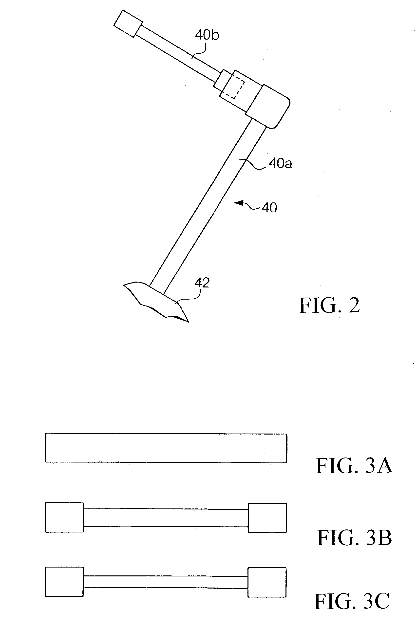
[0066] In the present embodiment, the struck portion 50 is constituted using only one sheet of the plate spring 53. Of course, it is possible to constitute the struck portion 50 by using multiple sheets of plate springs. For example, as shown in FIG. 9, it is possible to arrange three plate springs 53 each have the same size and shape independently for the low-pitch resister, middle-pitch register, and high-pitch register. In addition, it is possible to arrange three sheets of plate springs 531, 532, and 533 shown in FIG. 10, which are combined together in order to impart different weights to striking areas belonging to the low-pitch register, middle-pitch register, and high-pitch register respectively, so that weights of striking areas are gradually increased in a pitch descending order from higher pitches to lower pitches. Specifically, the plate spring 531 has a prescribed number of striking areas in correspondence with the hammer assemblies 40 of all the registe...
fourth example
(4) FOURTH EXAMPLE
[0067] In the present embodiment, the plate spring 53 of the struck portion 50 has a prescribed number of striking areas 53b in correspondence with the hammer assemblies 40. Instead, it is possible to integrally interconnect together all the striking areas 53b in the plate spring 53. Alternatively, it is possible to integrally interconnect together the striking areas 53b with respect to each of the three registers, i.e., low-pitch register, middle-pitch register, and high-pitch register. Even though the striking areas are integrally interconnected together with respect to each of the three registers so that substantially the same weight factors and deflections of strings of an upright piano are simulated with respect to all the registers, it is possible to noticeably improve key-touch responses upon depression of keys in comparison with the conventional keyboard structure that cannot reproduce deflections of strings struck by hammer felts in an electronic piano.
[00...
PUM
 Abstract
Description
Claims
Application Information
 - R&D
- Intellectual Property
- Life Sciences
- Materials
- Tech Scout
- Unparalleled Data Quality
- Higher Quality Content
- 60% Fewer Hallucinations
Browse by: Latest US Patents, China's latest patents, Technical Efficacy Thesaurus, Application Domain, Technology Topic, Popular Technical Reports.
© 2025 PatSnap. All rights reserved.Legal|Privacy policy|Modern Slavery Act Transparency Statement|Sitemap|About US| Contact US: help@patsnap.com


