Transaction terminal including imaging module

a technology of transaction terminal and imaging module, which is applied in the direction of atm details, instruments, individual entry/exit registers, etc., can solve the problems of pin information, lack of adequate security features of presently available transaction terminal, and numerous limitations of current available transaction terminals

Inactive Publication Date: 2003-07-17
HAND HELD PRODS
View PDF99 Cites 145 Cited by
  • Summary
  • Abstract
  • Description
  • Claims
  • Application Information

AI Technical Summary

Benefits of technology

0056] FIG. 7c is a business model diagram illustrating a method for marketing ad supplying a terminal according to the invention;
0057] FIGS. 7d-7g are perspective views of alternative apparatuses in which a security feature can be incorporated;
0058] FIG. 7h is a network diagram illustra...

Problems solved by technology

Unfortunately, currently available transaction terminals have been observed to exhibit numerous limitations.
For example, while presently available transaction terminals often are configured to prompt a user to enter personal identification (PIN) information, presently available transaction terminal lack adequate security features for assuring that the PIN information cannot be stolen, either by overriding of an encryption routine or by theft of encryption keys.
Presently available transaction terminals are also lacking in security features for monitoring presentation fraud.
For example, ...

Method used


Image

  • Transaction terminal including imaging module
  • Transaction terminal including imaging module
  • Transaction terminal including imaging module

Examples


example i

End of Example I

EXAMPLE II

Credit Transaction and Authorization

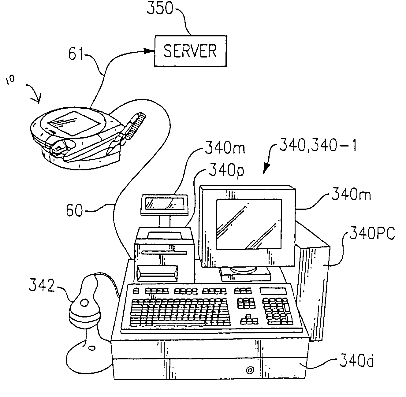
[0191] The following describes typical credit card transaction flow in U.S. networks for transactions initiated on a connected POS terminal.

[0192] The purchaser may initiate the transaction or be prompted by the POS device.

[0193] (A) Associate 312 initiates a new sale and begins scanning items;

[0194] (B) Purchaser 310 selects their payment option=credit;

[0195] (C) Terminal 10 saves customer selection=credit;

[0196] (D) Purchaser 310 inserts their card on the terminal MSR / SCR;

[0197] (E) Terminal 10 stores the credit card track data, waits for POS terminal request;

[0198] (F) Associate 312 completes the sale;

[0199] (G) POS 340 sends a message to the Terminal 10="send data";

[0200] (H) Terminal 10 replies to POS with track data and "credit" flag;

[0201] (I) POS 340 sends transaction amount, card data, terminal ID, etc. to host along with merchant data;

[0202] (J) Host 300 adds merchant data and forwards to authorization to networ...

example ii

End of Example II

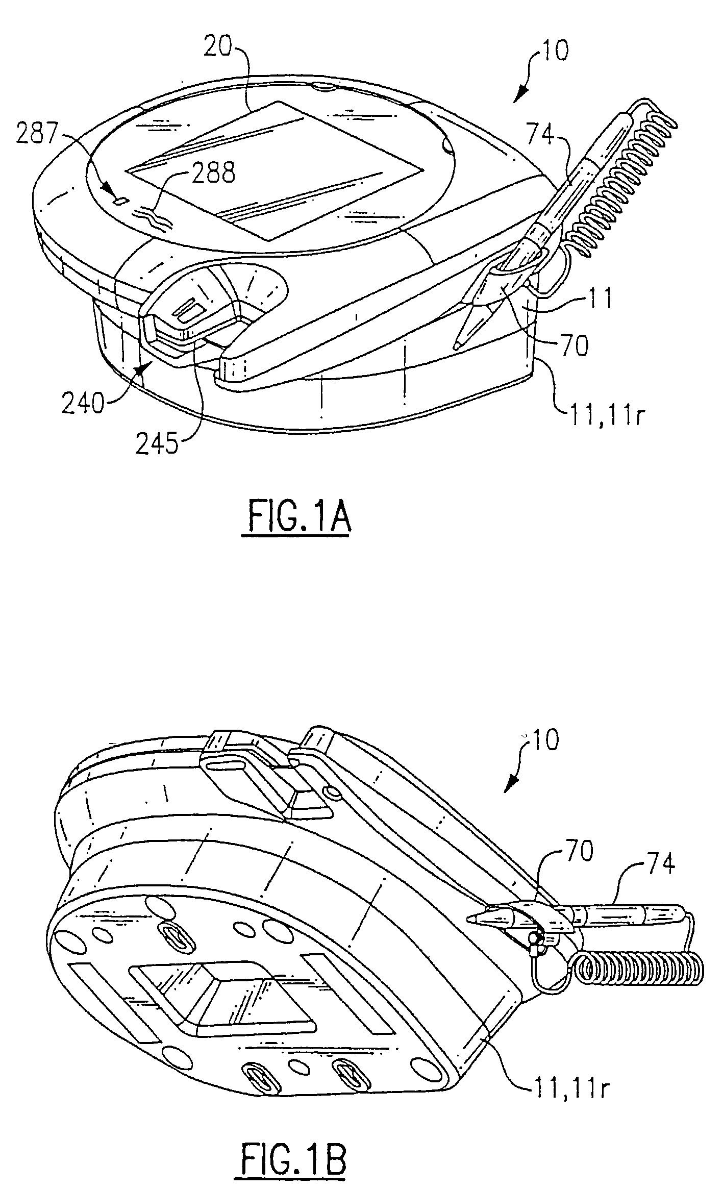
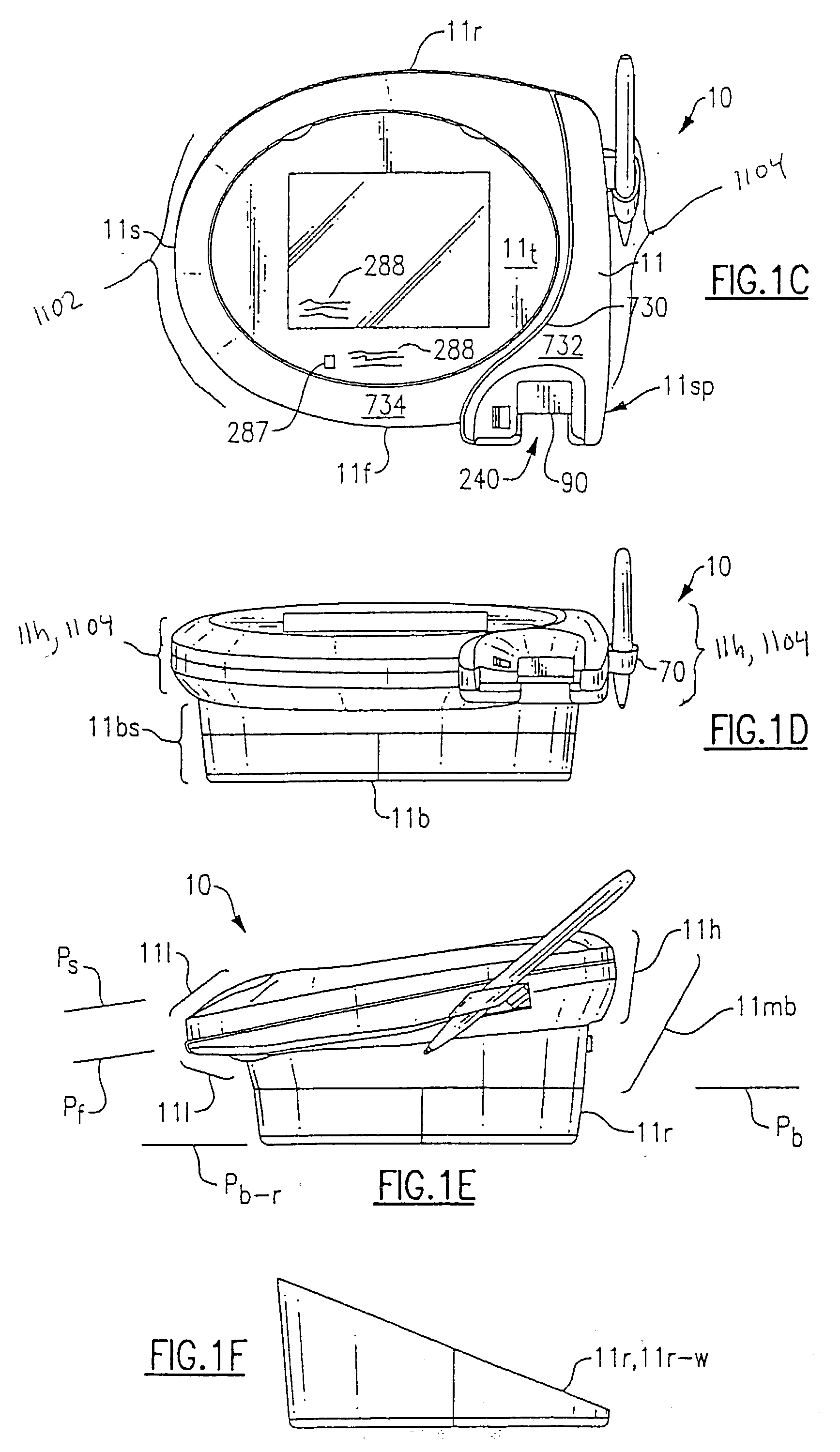
[0214] Referring to further aspects of the invention, housing 11 of terminal 10 includes a number of important features which will now be described in greater detail. Housing includes a, top 11t, a bottom 11b, a first side 11s, a second side 11s, a back end 11rr, and a front 11f. As best seen in FIG. 1e, top 11t which being substantially flat is angled downward slightly from back 11rr housing to front 11f. Because touch screen 20 is disposed substantially flush with top 11t of housing 11 the angling of top 11r enables a user to more readily observe indicia of housing when terminal 10 is disposed on a flat surface, e.g. a counter top. Housing 11 further includes a head 11h including housing top 11t and a base 11bs including bottom 11b.

[0215] Referring to aspects of bottom of housing 11b with reference to FIGS. 1j and 1k, bottom 11b of housing 11 includes at least three and preferably four or five feet 15, typically comprised of rubber adhesively attached material whi...


PUM


Abstract

A transaction terminal includes a housing, a touch screen, a card reader, an imaging module, and a decode circuit coupled to the imaging module. The imaging module in one embodiment is disposed in the housing so that an imaging axis extends rearward of the housing. In a typical use of the terminal a store clerk can easily move objects into a field of view of the terminal. The transaction terminal can be coupled to a POS network which remotely sends a trigger signal actuating the imaging module when an age-proof-require product is being purchased.

Description

[0001] This application is a continuation-in-part of U.S. application Ser. No. 10 / 044,137, entitled "Transaction Terminal Encryption Apparatus Comprising Encryption Mode Indicator", filed Jan. 11, 2002. This application also claims the priorities, under 35 U.S.C. .sctn.119, of U.S. Provisional Application Serial No. 60 / 348,738, entitled "Secure Information Input Apparatus Having Associated Secure Mode Indicator", filed Jan. 14, 2002 and U.S. Provisional Application Serial No. 60 / 347,708, entitled "Transaction Terminal Adapted for Ease of Use and Having Improved Security Features", filed Jan. 11, 2002. All of the above applications are expressly incorporated herein by reference.[0002] The invention relates to data collection devices in general and particularly to data collection devices including combine image capture and decoding functionality.BACKGROUND OF THE PRIOR ART[0003] "Transaction terminals" of the type having a data collection (e.g. mag stripe, smart card) input and signat...

Claims


Application Information

Patent Timeline
IPC IPC(8): G06Q20/00G07C9/00G07F7/10G07F19/00G07G1/00
CPCG06Q20/00G06Q20/341G06Q20/4014G06Q20/40145G07C9/00039G06K7/01G07F7/1008G07F19/20G07F19/205G07G1/0018G07F7/10G07C9/23G06Q20/20G06V40/1306G06F21/32G06F21/34G06K7/0013
Inventor GOMEZ, GARRISONFITCH, TIMOTHY R.MCCALL, MELVIN D.O'DONNELL, JAMESSMITH, GEORGE S. IISPERDUTI, DAVID
Owner HAND HELD PRODS
Why Eureka
Try Eureka