Conversion device for nature energy at sea

a technology of conversion device and nature energy, which is applied in the direction of electric generator control, machines/engines, mechanical equipment, etc., can solve the problems of inefficiency of device, easy damage of device, and inability to operate rods

Inactive Publication Date: 2003-07-24
SHU CHAO FU
View PDF7 Cites 26 Cited by
  • Summary
  • Abstract
  • Description
  • Claims
  • Application Information

AI Technical Summary

Problems solved by technology

The device is easily damaged by the strong wave impacted at the retention wall.
The device is not efficient when the seawater is at low tide.
Taiwan Patent No. 270962 discloses a power system powered by accumulated nature energy sources which makes use of a device vibrating in accordance with the wave ...

Method used


Image

  • Conversion device for nature energy at sea
  • Conversion device for nature energy at sea
  • Conversion device for nature energy at sea

Examples


Embodiment Construction

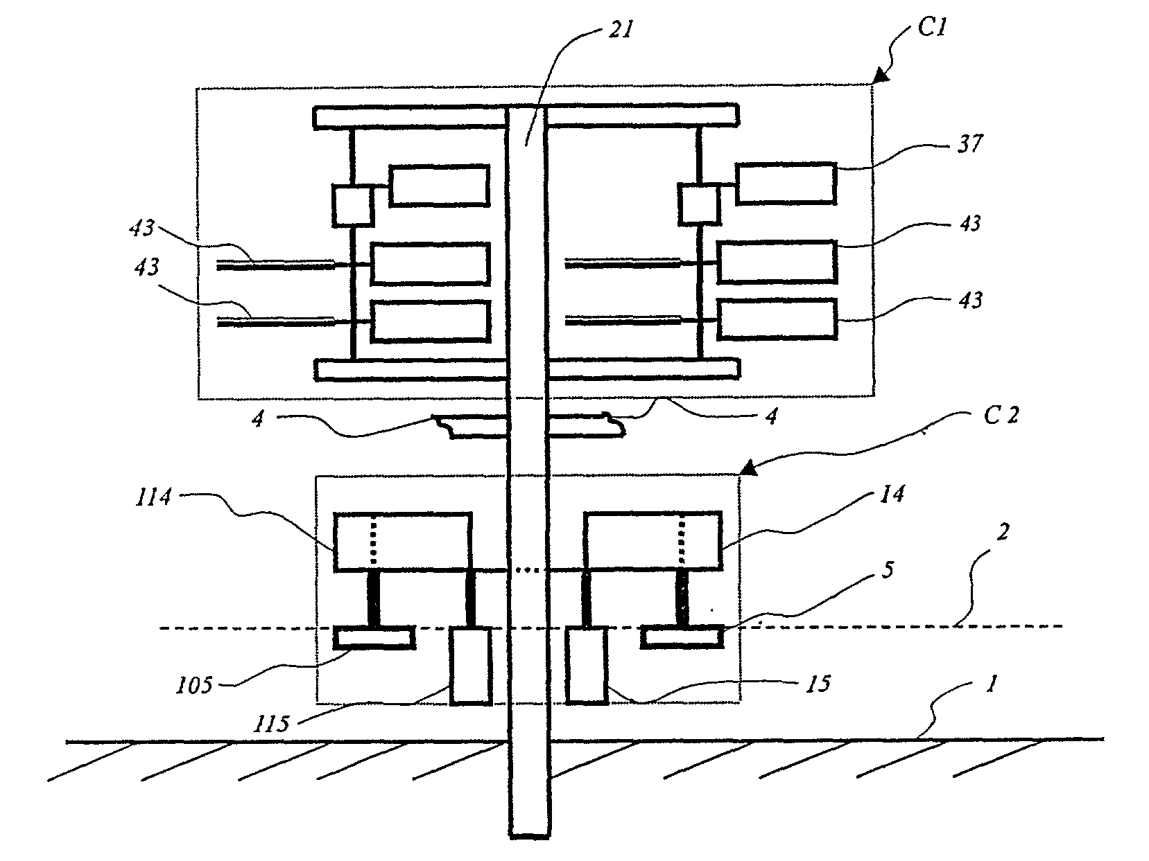
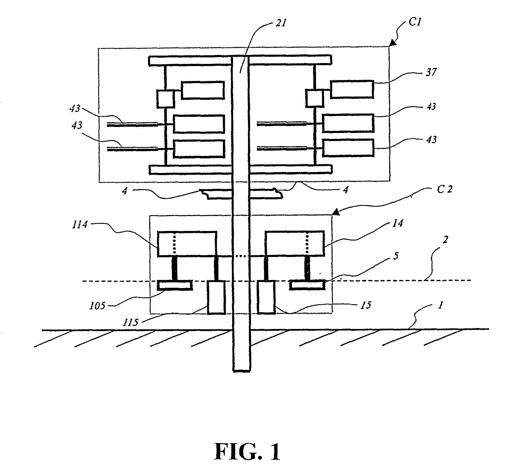
[0035] FIG. 1 is a schematic view showing a conversion device for natural energy at sea in accordance with the present invention. The device is divided into a top layer and a bottom layer. The top layer C1 is a wind energy conversion device for accessing wind energy and is then converted into high-pressure air energy. The bottom layer C2 is a float-type wave energy conversion device to access wave energy and is then converted into high-pressure air energy. These two devices are supported by a supporting body 21 having one end being mounted onto the seabed 1 and the middle section is connected to other support bodies 21 by an interlinking rod 4. These two devices can be used for the conversion of wind energy or wave energy.

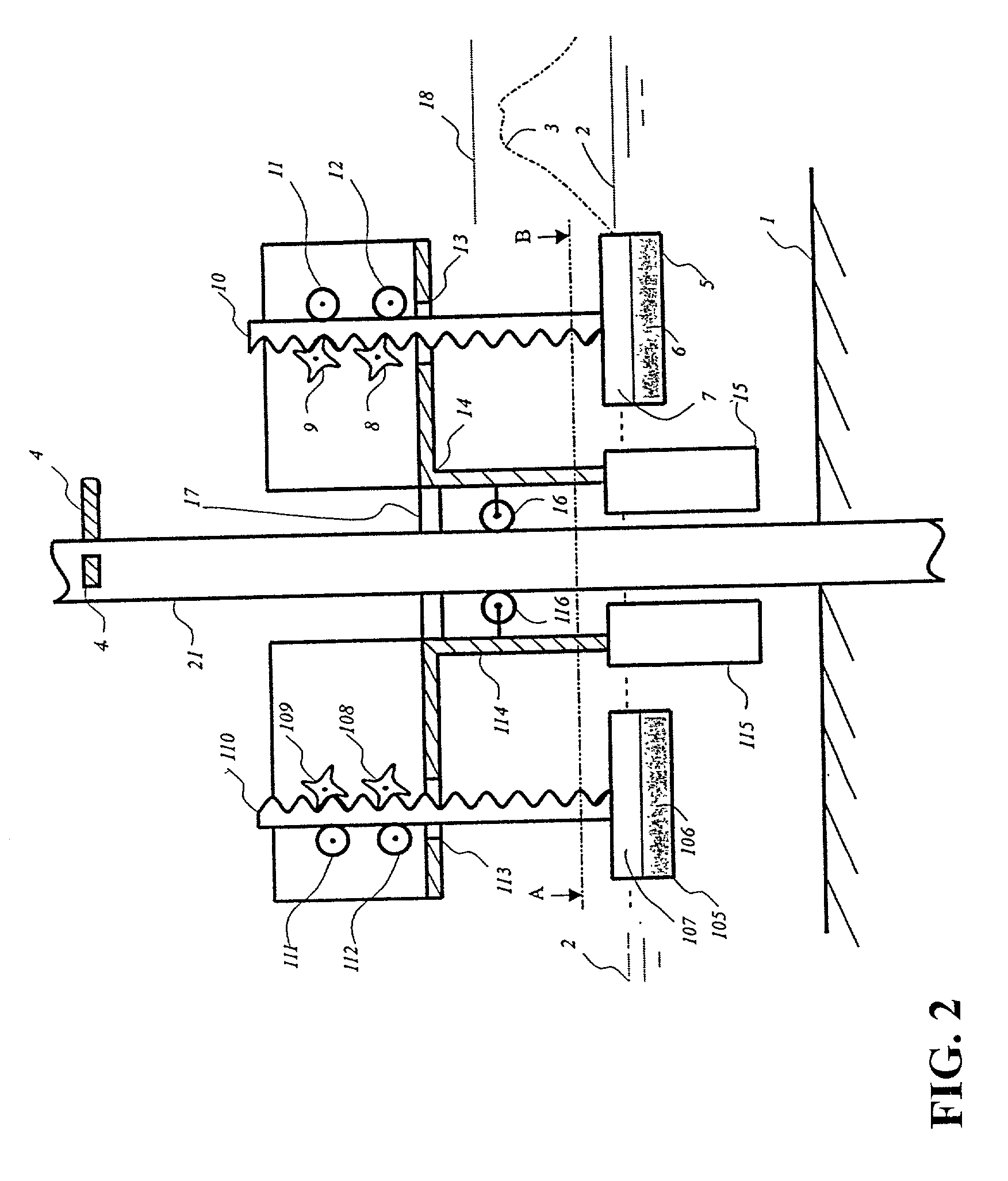
[0036] FIG. 2 is a schematic view showing a float-type wave energy conversion device in accordance with the present invention.

[0037] A support body 21, a float, a flat floating cylinder 5 and a transmission mechanism support the device. One end of the support body ...


PUM


Abstract

A conversion device for nature energy at sea is disclosed. The device effectively accesses low energy wave and wind and converts the energy into operable energy for application. The device is applicable to the change of tide and the size of wind power and is suitable for use at the shallow sea side.

Description

[0001] (a) Field of Technical Art[0002] The present invention relates, in general, to a conversion device for converting nature energy at sea, such as wave energy and wind energy, to other useful energy to be used at a later time.[0003] (b) Brief Description of the Prior Art[0004] In the prior art various types of energy extraction and conversion devices have been proposed. For example, Taiwan Patent Nos. 246162, 252182, 270,962, and 325820, and U.S. Pat. Nos. 5,708,305, 5,808,368, 4,101,244, etc disclose devices used in producing useful energy such as electrical energy by converting energy of wind, water and wave.[0005] Taiwan Patent No. 246162 discloses a generator powered by wave and the device can only be located at the wave retention wall and the push of the wave drives the turbine of the generator to produce useful electrical energy. The device is easily damaged by the strong wave impacted at the retention wall.[0006] Taiwan Patent No. 252182 discloses a wave generator which u...

Claims


Application Information

Patent Timeline
IPC IPC(8): F03B13/18F03D9/00
CPCF03B13/186Y02E10/72Y02E10/38F03D9/008Y02E10/727Y02E10/30F03D80/70F03D13/25
Inventor SHU, CHAO-FU
Owner SHU CHAO FU
Why Eureka
Try Eureka