Electric motor drive system and method

Inactive Publication Date: 2003-07-24
VALEO ELECTRICAL SYST
View PDF11 Cites 70 Cited by
  • Summary
  • Abstract
  • Description
  • Claims
  • Application Information

AI Technical Summary

Problems solved by technology

One problem with this arrangement was that the circuit board had to be aligned perpendicular to the axis of the armature of the electric motor so that the brushes could be properly aligned with the commutator.
Another problem with the prior art designs is that when the brushes were situated on the board which required that the board be situated on a plane, which was substantially perpendicular to the axis of the armature.

Method used


Image

  • Electric motor drive system and method
  • Electric motor drive system and method
  • Electric motor drive system and method

Examples


Embodiment Construction

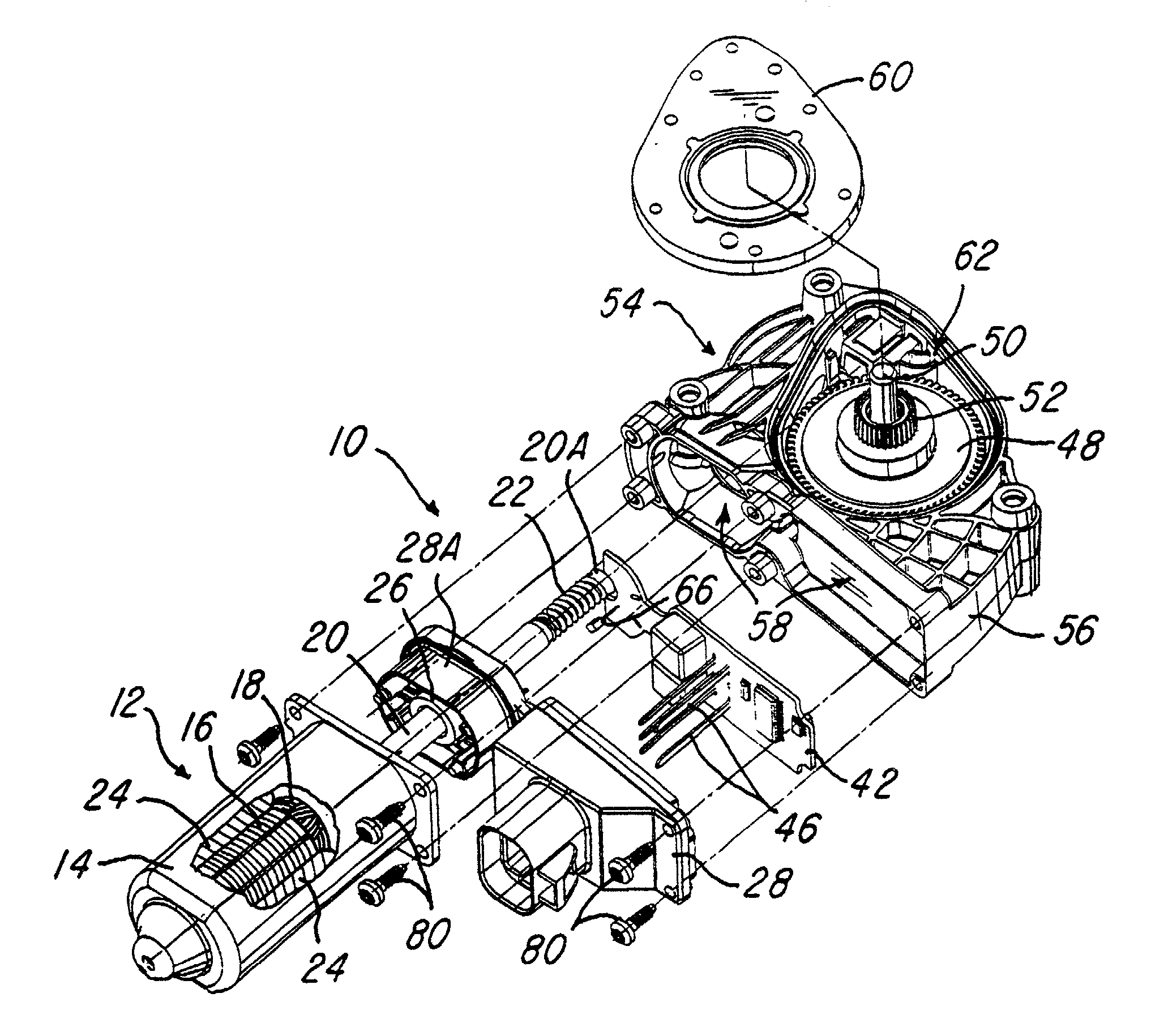
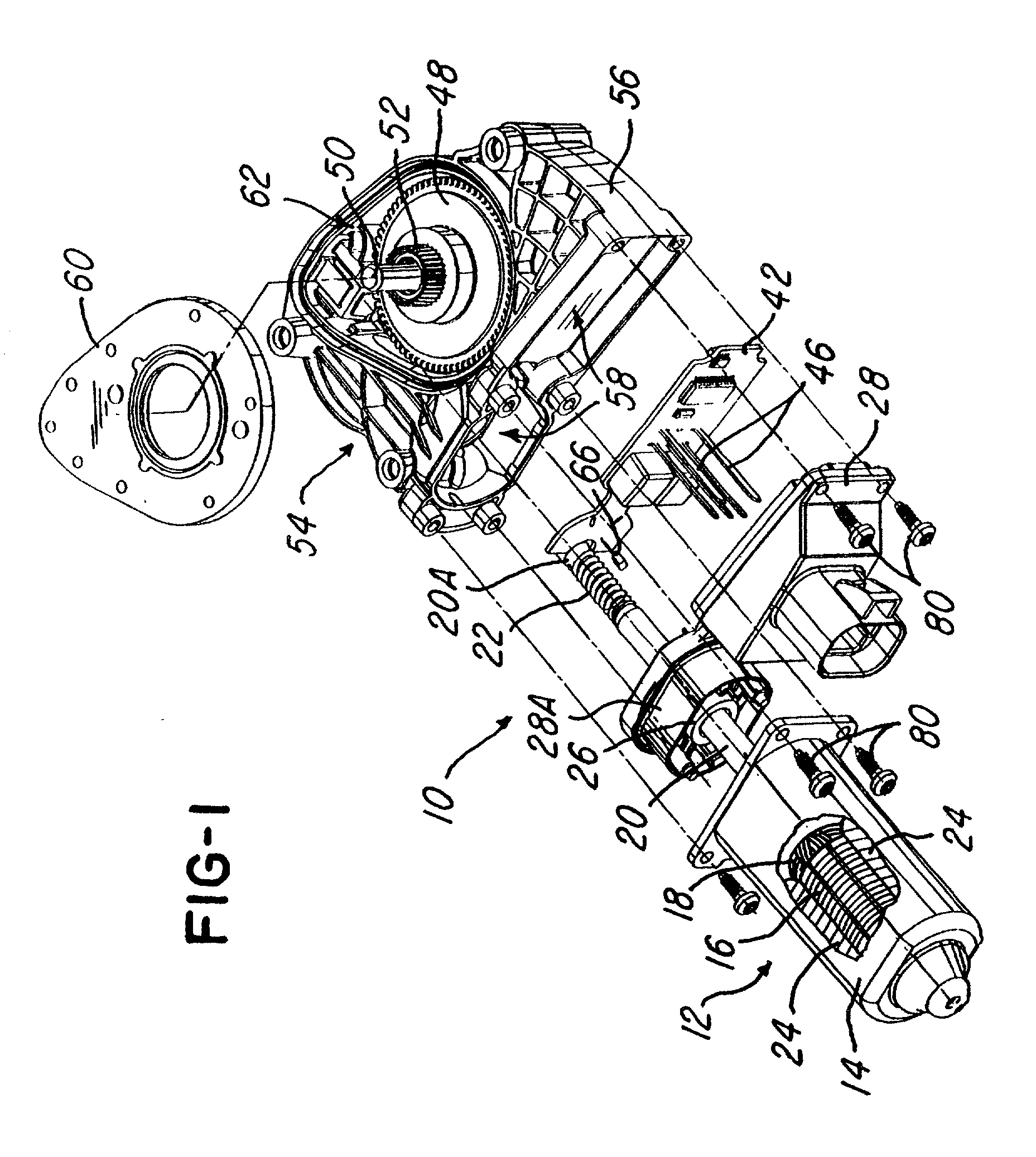
[0021] Referring now to FIG. 1, a drive system or unit 10 is shown. The drive system 10 comprises a drive motor 12 situated in a motor housing 14 which receives a rotor 16 comprising a plurality of windings 18. The rotor 16 is mounted on an armature 20 having a drive gear 22 towards an end 20a of the armature 20. It should be appreciated that the housing 14 comprises a pair of permanent magnets 24, which cause the armature 20 to rotate when a current is applied to the plurality of windings 18 by a commutator 26 in a manner conventionally known.

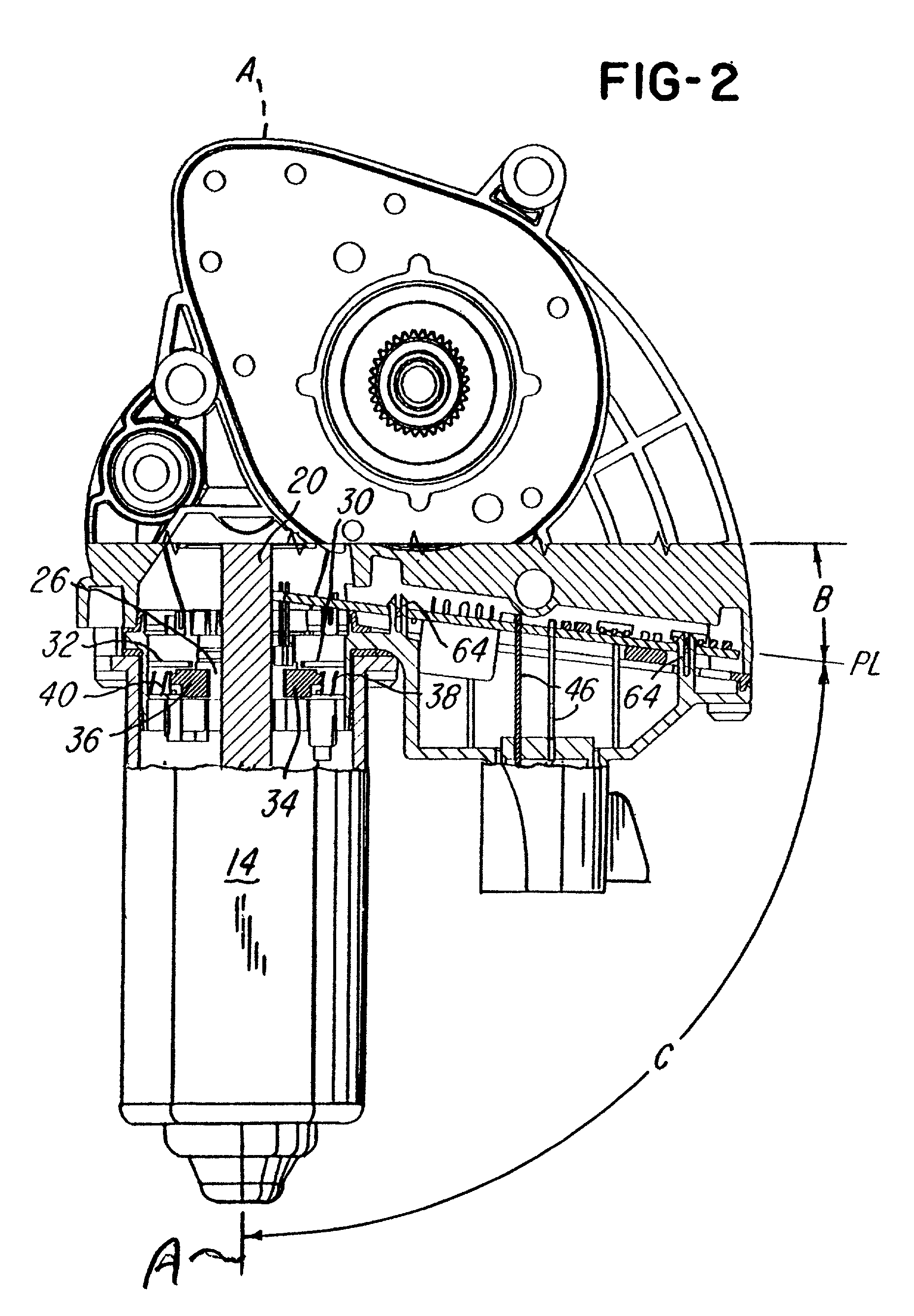
[0022] The system or drive unit 10 further comprises a brush housing 28 having a pair of brush holders 30 and 32 (FIG. 2) as illustrated in FIGS. 3 and 3A, brush holder 30 is defined by a wall 30a (FIGS. 3 and 3A). Note that the brush holders 30 and 32 receive the brushes 34 and 36 which are biased by springs 38 and 40, respectively, towards an axis A (FIG. 2) of armature 20.

[0023] The system or drive unit 10 further comprises the circuit boar...


PUM


Abstract

An electric motor system and method are shown having a circuit board arranged in a plane that lies in a predetermined angle relative to an axis to an armature of the electric motor. In one embodiment the predetermined angle is an acute angle and the plane is not perpendicular to an axis of an armature of the motor 10. Brushes are located remotely from the board.

Description

[0001] 1. Field of the Invention[0002] This invention relates to a commutator motor drive gear system and method and more particularly to a motor having a circuit board that it lies in a plane that is not perpendicular to an axis of the drive motor.[0003] 2. Description of Prior Art[0004] In the past, printed circuit boards comprised circuits for controlling electrical motors, such as window lift motors, seat drive motors and other electrical motors that are used in vehicles. It has been convenient to situate the circuit board near the motor. U.S. Pat. No. 5,528,093 discloses integrating electronics with a drive unit. A printed-circuit board, which accommodates the electronic components and which is designed, at the same time, as a brush-holder plate for the commutator motor, is arranged, together with an electronic housing, parallel to housing flanges of a motor housing of a gear housing. The printed circuit board of the drive unit is covered on its one axial side by the motor hous...

Claims


Application Information

Patent Timeline
Patent Type & Authority Applications(United States)
IPC IPC(8): H02K5/14H02K5/22H02K7/116H02K11/00H02K11/04
CPCH02K5/148H02K5/225H02K11/0084H02K11/0021H02K7/1166H02K11/215H02K11/38
Inventor MAO, WEIXINGEVERHART, JON C. JR.CAUSSAT, THIERRY R.
Owner VALEO ELECTRICAL SYST
Why Eureka
Try Eureka