Device for controlling a variable-angle vane via a pinch connection

a technology of a pinch connection and a variable angle vane, which is applied in the direction of couplings, machines/engines, liquid fuel engines, etc., can solve the problems of low level of precision, error in the range 0.4.degree. to 0.6.degree. in common practice, so as to eliminate the lack of precision in turning the link, the effect of reducing the drawback

Inactive Publication Date: 2003-07-31
SN DETUDE & DE CONSTR DE MOTEURS DAVIATION S N E C M A
View PDF3 Cites 13 Cited by
  • Summary
  • Abstract
  • Description
  • Claims
  • Application Information

AI Technical Summary

Benefits of technology

0006] The present invention thus seeks to mitigate such drawbacks by proposing a control device using fixing means for the link which enable it to be held without slack on the vane pivot. Another object of the invention is to eliminate lack of precision in turning.

Problems solved by technology

Nevertheless, in those documents, the precision with which the control link turns relatively to the vane pivot leaves an error in the range 0.4.degree. to 0.6.degree. in common practice.
This low level of precision stems from the fact that clearance exists between the various parts due to the assembly tolerances of the control device.
This gives rise to lack of precision in turning the link which is particularly harmful to proper operation of the assembly.

Method used


Image

  • Device for controlling a variable-angle vane via a pinch connection
  • Device for controlling a variable-angle vane via a pinch connection
  • Device for controlling a variable-angle vane via a pinch connection

Examples


first embodiment

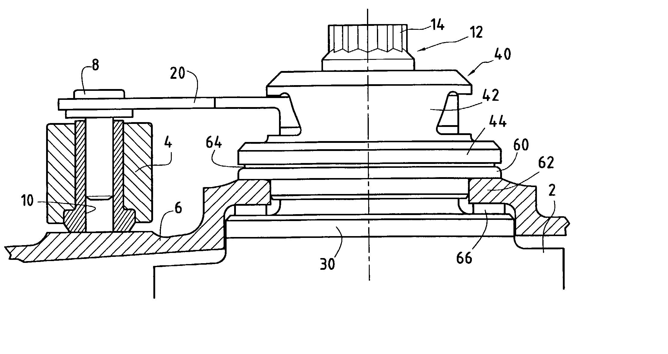
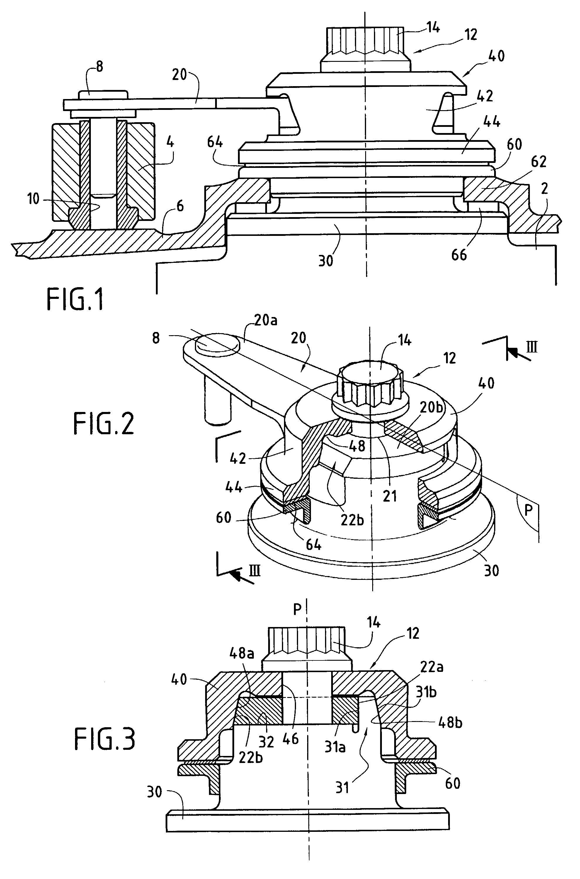
[0032] In the invention as shown in FIGS. 2 and 3, the pivot 30 of the vane of the control device has a rigid side portion 31 projecting longitudinally from a top face 32 of the pivot 30 in the vicinity of the edge thereof. This rigid portion is made integrally with the pivot 30, it has a plane inside face 31a that is substantially parallel to the plane P and it has a plane outside face 31b which is inclined relative to the plane P. The plane inside face 31a of the rigid portion may also be slightly inclined relative to the plane P in order to hold the link 20 better on the pivot 30.

[0033] The second end 20b of the link 20 presents an orifice 21 in which there is engaged with clearance the screw 14 (or else a threaded rod secured to the vane pivot), and said end bears against the face 32 of the pivot 30. This end 20b of the link has a first side face 22a which is substantially parallel to the longitudinal midplane P of the link and which bears against the plane inside face 31a of th...

third embodiment

[0043] Reference is now made to FIGS. 6 and 7 which show the invention. In this embodiment, the vane pivot 30 of the control device has two slots 34a and 34b that are substantially parallel to the plane P and that are formed between a central block 35 of the pivot 30 and two thin side portions 36a and 36b forming flexible tongues. Each of these thin side portions has a respective outside face 37a or 37b which is inclined relative to the longitudinal midplane P of the link.

[0044] The second 20b of the link 20 bears against the top face 32 of the central block 35 of the pivot 30. This end 20b is of channel section having two flanges 24a and 24b engaged in the slots 34a and 34b respectively of the vane pivot 30.

[0045] The screw 14 is inserted successively through the orifice 46 of the clamping cap, through the orifice 21 in the second end of the link, and into the orifice formed in the vane pivot. When a screw-and-nut system is used, the threaded rod secured to the vane pivot passes li...

fourth embodiment

[0047] In the invention as shown in FIGS. 8, 9A, and 9B, the vane pivot 30 of the control device presents a block 35 having two plane side faces 38a and 38b which are substantially parallel to the plane P and symmetrical about said plane P.

[0048] The second end 20b of the link 20 bears against the top face 32 of the block 35. This end 20b is of channel section having two flanges 24a and 24b which bear against the corresponding plane side faces 38a and 38b of the vane pivot 30.

[0049] Pieces of shim 50a and 50b are interposed between the inclined side faces 48a and 48b of the transverse passage 48 formed in the cylindrical portion 42 of the clamping cap 40 and the flanges 24a and 24b at the second end 20b of the link. The top portions of these pieces of shim 50a and 50b have first outside faces 51a and 51b that are inclined relative to the plane P.

[0050] The screw 14 is inserted successively through the orifice 46 of the clamping cap, through the orifice 21 in the second end of the li...


PUM


Abstract

A device for controlling a variable-angle vane for a stator of a turbomachine compressor, the device comprising a link, connection means forming a hinge between a first end of the link and a control ring, fixing means for fixing a second end of the link on a pivot of a vane to be controlled, and pinch means acting transversely relative to a longitudinal midplane of the link to lock the second end of the link in rotation without slack on the pivot.

Description

[0001] The present invention relates to controlling vanes having a variable setting angle. A particular application for the invention lies in the field of aviation, in particular for controlling the angular positions of air inlet guide vanes in the compressors of turbomachines, such as airplane turbomachines.[0002] Known devices for controlling variable-setting vanes in a turbomachine generally comprise a control member in the form of a ring surrounding the casing of the turbomachine and a plurality of levers or links, each link having a first end connected to the control ring via a hinge and a second end mounted on the pivot of a respective vane.[0003] The angular position of the vanes is changed synchronously by turning the ring about the axis of the turbomachine. In order to be able to follow the turning movement of the ring, the connection between each link and the ring has at least one degree of freedom in rotation about an axis extending substantially radially relative to the ...

Claims


Application Information

Patent Timeline
Patent Type & Authority Applications(United States)
IPC IPC(8): F01D17/16F04D29/46F04D29/56
CPCF01D17/16F01D17/162F04D29/563Y10T403/32172Y10T403/50Y10T403/32073Y10T403/54
Inventor BOURU, MICHEL
Owner SN DETUDE & DE CONSTR DE MOTEURS DAVIATION S N E C M A
Why Eureka
Try Eureka