
Refrigeration system

a refrigerant circuit and refrigeration technology, applied in the field of refrigeration systems, can solve the problems of compressor damage, excessive refrigerant filling amount relative to the required refrigerant circulation amount, and abnormal so as to accurately detect the lack, the degree of opening of the electronic expansion valve (14) can be increased, and the high pressure of the refrigerant circuit can be reduced.

Inactive Publication Date: 2011-02-15
DAIKIN IND LTD
View PDF7 Cites 14 Cited by
  • Summary
  • Abstract
  • Description
  • Claims
  • Application Information

AI Technical Summary

Benefits of technology

The present invention provides a refrigeration system that can selectively operate in either the air-cooled or water-cooled operation mode. The system includes an air-cooled condenser and a water-cooled condenser, an electronic expansion valve, and an evaporator. The system is designed to prevent the high pressure of the refrigerant circuit from increasing during the water-cooled operation mode. The invention solves the problem of excess refrigerant in the air-cooled circuit and ensures a sufficient amount of return oil to the compressor while inhibiting the high pressure from increasing. The system includes a controller means that turns on the air-cooled condenser fan if the amount of circulation of the refrigerant through the refrigerant circuit is in short supply. The technical effect of the invention is to prevent damage to the compressor and ensure a sufficient amount of return oil to the compressor while inhibiting the high pressure from increasing during the water-cooled operation mode.

Problems solved by technology

However, if the water-cooled operation mode is run at that refrigerant filling amount, the refrigerant filling amount becomes excessive relative to the required refrigerant circulation amount.
As a result, surplus refrigerant is accumulated in the form of liquid in the water-cooled condenser, leading to the possibility that the high pressure of the refrigerant circuit may increase to an abnormal level.
As a result, the amount of refrigerating machine oil for providing lubrication of the compression mechanism of the compressor or the like is in short supply, thus leading to the possibility that the compressor may be damaged.

Method used


Image

  • Refrigeration system
  • Refrigeration system
  • Refrigeration system

Examples


Embodiment Construction

[0040]Hereinafter, an embodiment of the present invention will be described in detail with reference to the accompanying drawings.

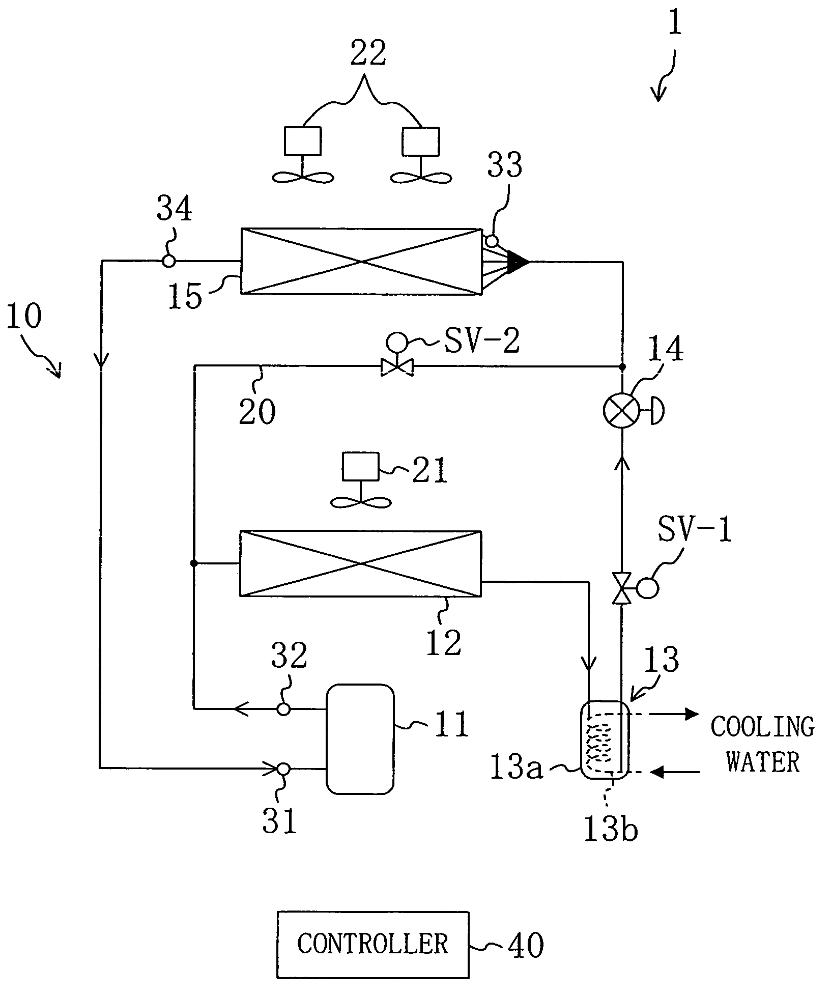
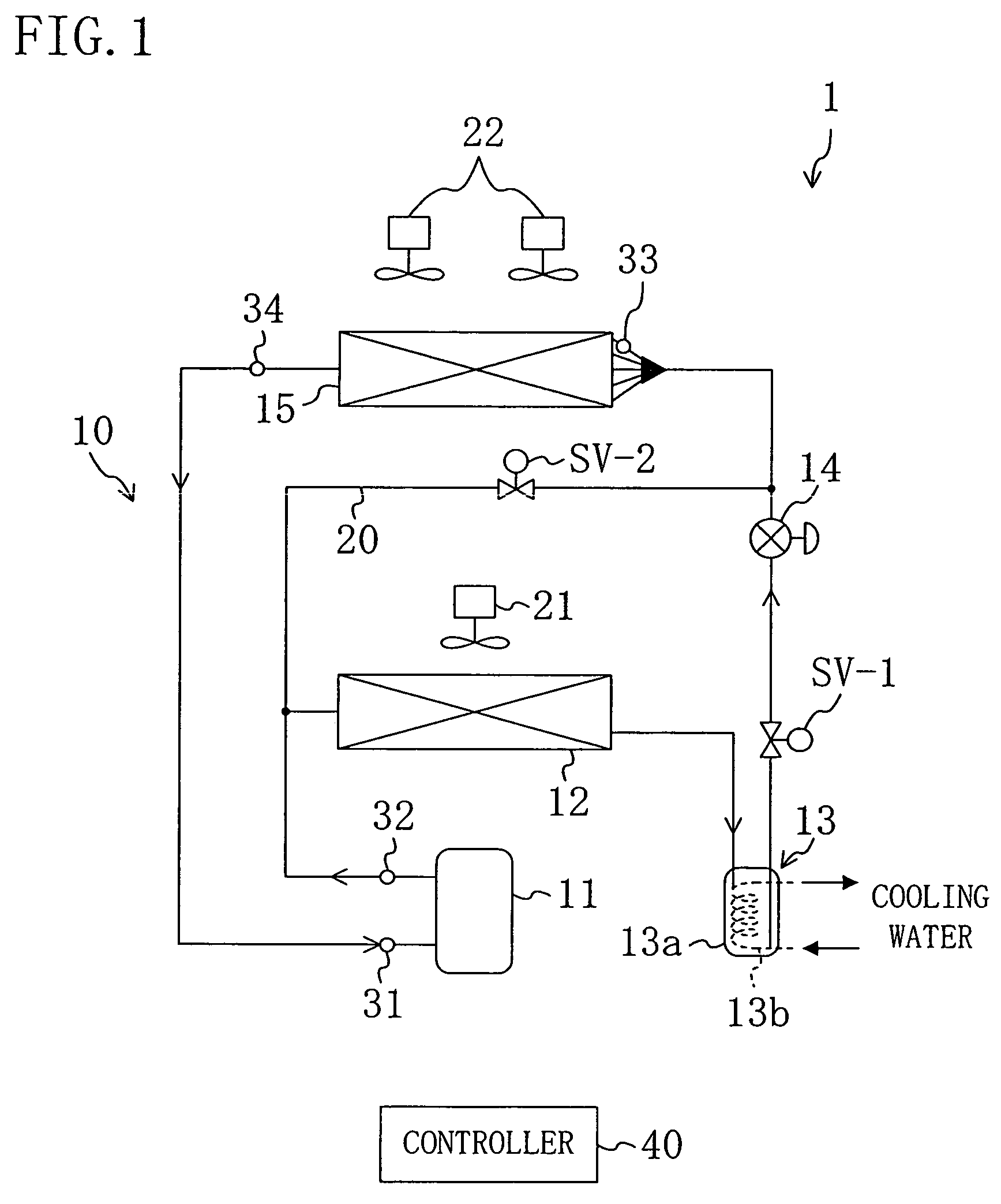
[0041]A refrigeration system (1) of the present embodiment is to provide cooling of the inside of the compartment of a container for use in marine transport or the like. As shown in FIG. 1, the refrigeration system (1) is provided with a refrigerant circuit (10) through which refrigerant is circulated to operate a vapor compression refrigeration cycle.

[0042]The refrigeration system (1) includes, as its essential equipment, a compressor (11), an air-cooled condenser (12), a water-cooled condenser (13), an electronic expansion valve (14), and an evaporator (15) which are connected in series.

[0043]The compressor (11) is formed by a scroll compressor of the fixed displacement type. The air-cooled condenser (12) is arranged outside the compartment. An air-cooled condenser fan (21) for supplying outside compartment air to the air-cooled condenser (12) is dispos...


PUM


Abstract

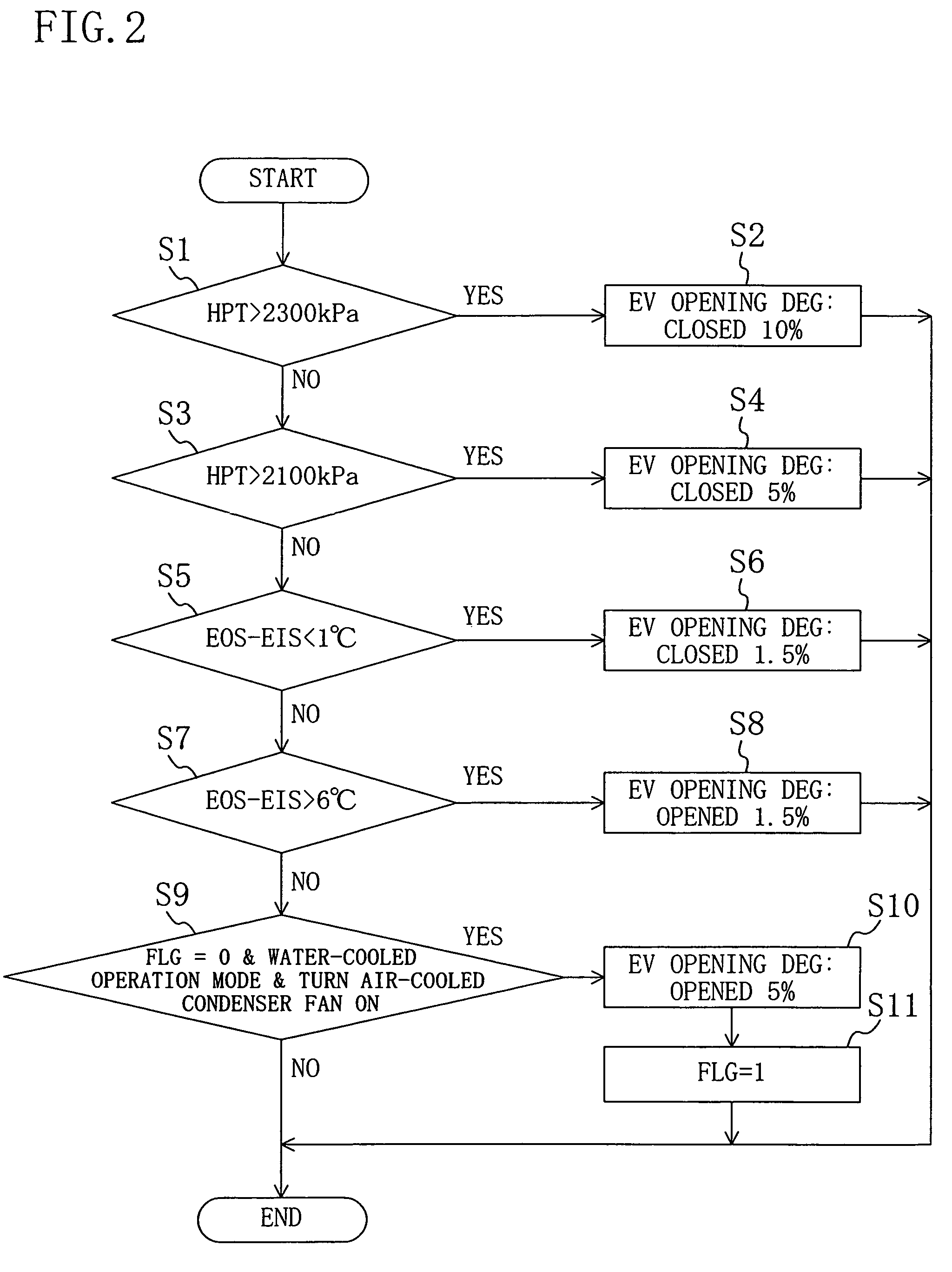
If the degree of opening of an electronic expansion valve (14) continues to remain below a specified degree of opening or if the degree of superheat of an evaporator (15) continues to remain above a predetermined degree of superheat, it is determined that the refrigerant circulation amount is in short supply in the water-cooled operation mode, and an air-cooled condenser fan (21) is tuned on.

Description

TECHNICAL FIELD[0001]The present invention relates generally to a refrigeration system in which either one of a water-cooled condenser and an air-cooled condenser is used as a cold heat source to condense refrigerant. This invention relates more particularly to a technique for the return back of oil to a compressor of such a refrigeration system.BACKGROUND ART[0002]Refrigeration systems, used for marine containers et cetera to provide cooling of the inside of the container compartments, have been known in the art for many years. In a marine-container refrigeration system, air may not be available as a cold heat source due to the shipboard equipment. To cope with this, there are proposed refrigeration systems such as one disclosed in JP-A-2004-340525. This refrigeration system, which is equipped with an air-cooled condenser and a water-cooled condenser, operates, selectively in response to the container installation situation, either in an air-cooled operation mode in which the refri...

Claims


Application Information

Patent Timeline
Patent Type & Authority Patents(United States)
IPC IPC(8): F25B39/04
CPCF25B49/027F25B6/04F25B2339/047F25B2400/19F25B2600/111F25B2600/21F25B2600/2513Y02B30/743Y02B30/70
Inventor KAWAKATSU, NORIYASUTANAKA, SHIGETO
Owner DAIKIN IND LTD
Learn More