Device for controlling a variable-angle vane via a slack-free connection

a technology of slack-free connection and variable angle vane, which is applied in the direction of machines/engines, couplings, liquid fuel engines, etc., can solve the problems of low level of precision, lack of precision in turning the link, and error in the range 0.4.degree. to 0.6.degree. in common practice, so as to eliminate the lack of precision in turning. , the effect of reducing the drawback

Inactive Publication Date: 2004-09-28
SN DETUDE & DE CONSTR DE MOTEURS DAVIATION S N E C M A
View PDF9 Cites 3 Cited by
  • Summary
  • Abstract
  • Description
  • Claims
  • Application Information

AI Technical Summary

Benefits of technology

The present invention thus seeks to mitigate such drawbacks by proposing a control device using fixing means for the link which enable it to be held without slack on the vane pivot. Another object of the invention is to eliminate lack of precision in turning.
As a result, the second end of the link is positioned without slack on the vane pivot by means of the inclined planes made in the radial recess and the second end of the link. The second end of the link is prevented from moving on the vane pivot by means of the clamping cap, and it is prevented from turning relative thereto by the fixing means. Thus, the precision of the turning drive imparted by the link to the vane pivot is improved.
A groove formed in the inside surface of the clamping cap and in which part of the second end of the link is engaged serves advantageously to prevent the clamping cap from turning relative to the other parts.

Problems solved by technology

Nevertheless, in those documents, the precision with which the control link turns relatively to the vane pivot leaves an error in the range 0.4.degree. to 0.6.degree. in common practice.
This low level of precision stems from the fact that clearance exists between the various parts due to the assembly tolerances of the control device.
This gives rise to lack of precision in turning the link which is particularly harmful to proper operation of the assembly.

Method used


Image

  • Device for controlling a variable-angle vane via a slack-free connection
  • Device for controlling a variable-angle vane via a slack-free connection

Examples


Embodiment Construction

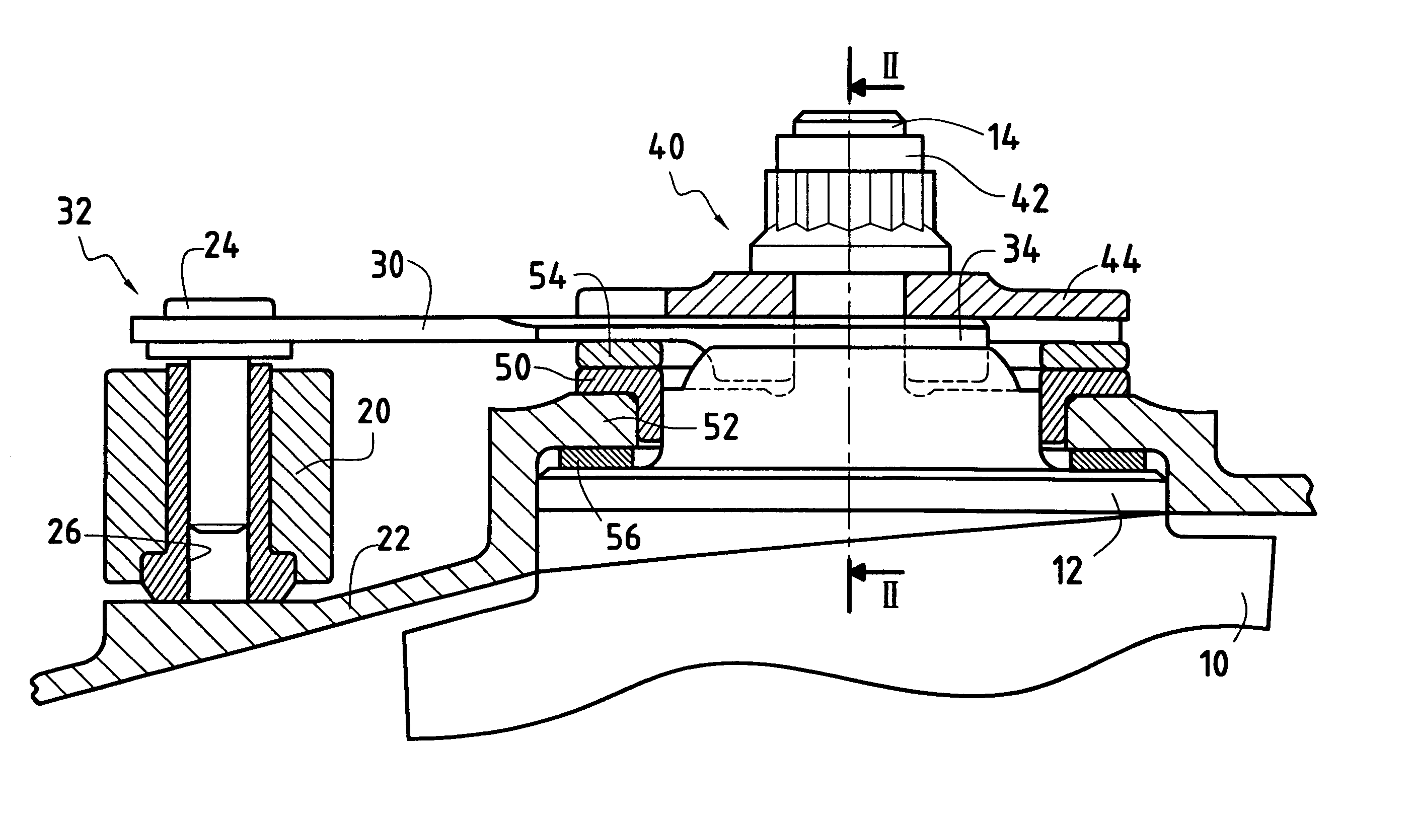
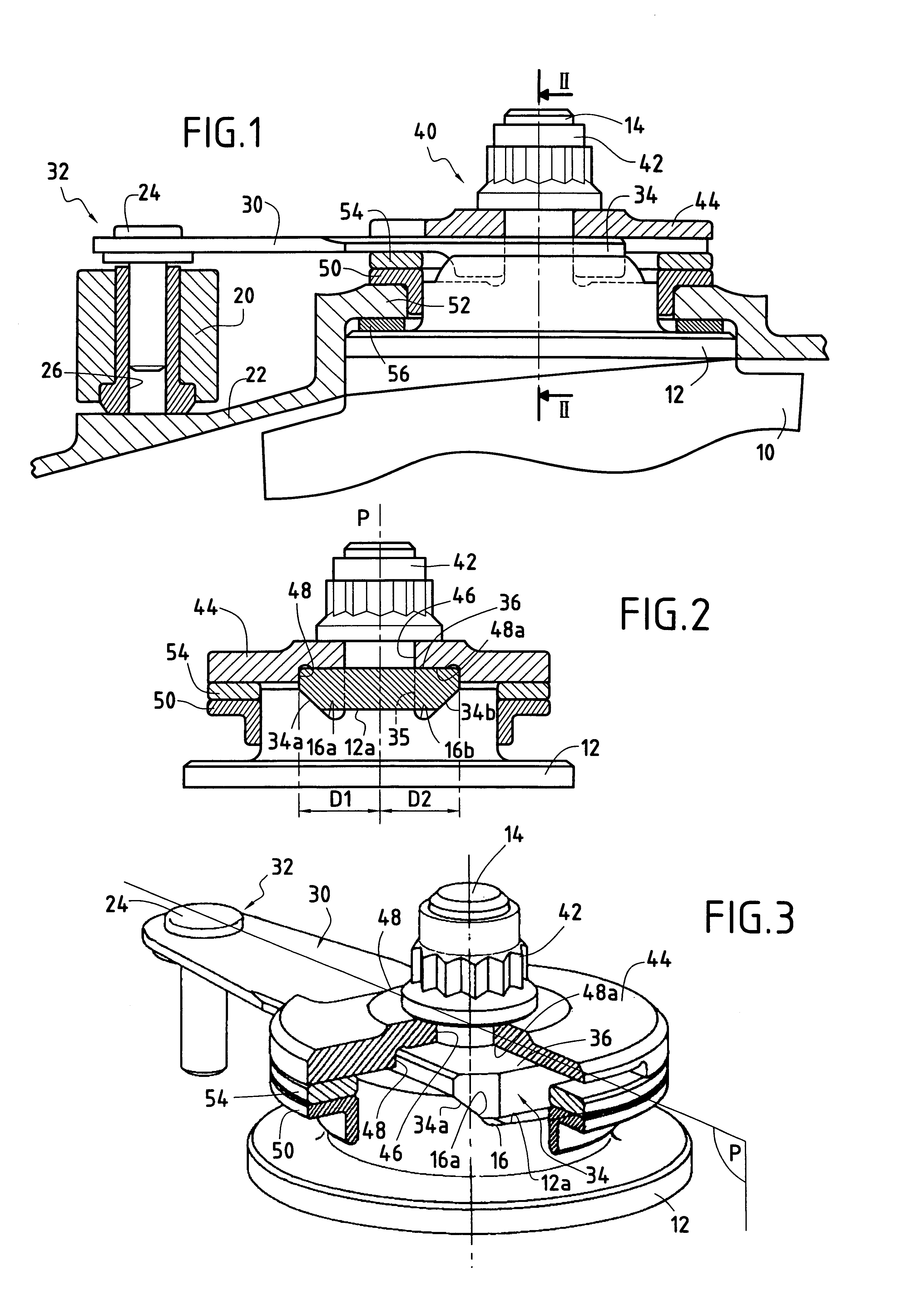
FIG. 1 shows a small part of a turbomachine, e.g. an airplane turbojet, provided with vanes 10 of variable setting angle. By way of example, these vanes are guide vanes at the inlet to a compressor of the turbomachine, and they are distributed around the axis of the turbomachine. In FIG. 1, only one vane is shown.

In well-known manner, the angular position of the vanes 10 is controlled by means of a control ring 20 surrounding a casing 22 of the turbomachine (shown in part only in FIG. 1), and a plurality of links 30. Each link 30 has a first end 32 connected to the control ring 20 via hinge-forming connection means. For example the hinge is constituted by a pin or finger 24 passing through the first end 32 of the link 30 and engaged in a housing 26 in the control ring 20.

A second end 34 of the link 30 is mounted on a pivot 12 of the vane 10 via fixing means 40. The fixing means 40 shown in FIG. 1 are conventionally formed by a screw-and-nut system comprising an axial threaded rod 14...


PUM


Abstract

A device for controlling a variable-angle vane for a stator of a turbomachine compressor, the device comprising a link, connection means forming a hinge between a first end of the link and a control ring, and fixing means for fixing a second end of the link on a pivot of a vane to be controlled, a radial recess formed in the vane pivot for receiving the second end of the link, the recess having at least one plane edge inclined relative to a longitudinal midplane of the recess and co-operating with a corresponding inclined edge of the second end of the link, and a clamping cap bearing against the second end of the link and on which the fixing means act, the clamping cap having an inside surface providing plane contact with the outside face of the second end of the link in order to maintain the second end of the link against the vane pivot without slack by means of contact between theinclined edges.

Description

The present invention relates to controlling vanes having a variable setting angle. A particular application for the invention lies in the field of aviation, in particular for controlling the angular positions of air inlet guide vanes in the compressors of turbomachines, such as airplane turbomachines.Known devices for controlling variable-setting vanes in a turbomachine generally comprise a control member in the form of a ring surrounding the casing of the turbomachine and a plurality of levers or links, each link having a first end connected to the control ring via a hinge and a second end mounted on the pivot of a respective vane.The angular position of the vanes is changed synchronously by turning the ring about the axis of the turbomachine. In order to be able to follow the turning movement of the ring, the connection between each link and the ring has at least one degree of freedom in rotation about an axis extending substantially radially relative to the ring. Nevertheless, s...

Claims


Application Information

Patent Timeline
Patent Type & Authority Patents(United States)
IPC IPC(8): F01D17/00F01D17/16F04D29/56F04D29/40F04D27/00F04D29/46
CPCF01D17/16F01D17/162F04D29/563Y10T403/54Y10T403/32172Y10T403/32073Y10T403/50
Inventor BOURU, MICHEL
Owner SN DETUDE & DE CONSTR DE MOTEURS DAVIATION S N E C M A
Why Eureka
Try Eureka