Device for controlling a variable-angle vane via a pinch connection
a technology of a pinch connection and a variable angle vane, which is applied in the direction of couplings, machines/engines, liquid fuel engines, etc., can solve the problems of low level of precision, error in the range 0.4.degree. to 0.6.degree. in common practice, so as to eliminate the lack of precision in turning the link, the effect of reducing the drawback
- Summary
- Abstract
- Description
- Claims
- Application Information
AI Technical Summary
Benefits of technology
Problems solved by technology
Method used
Image
Examples
first embodiment
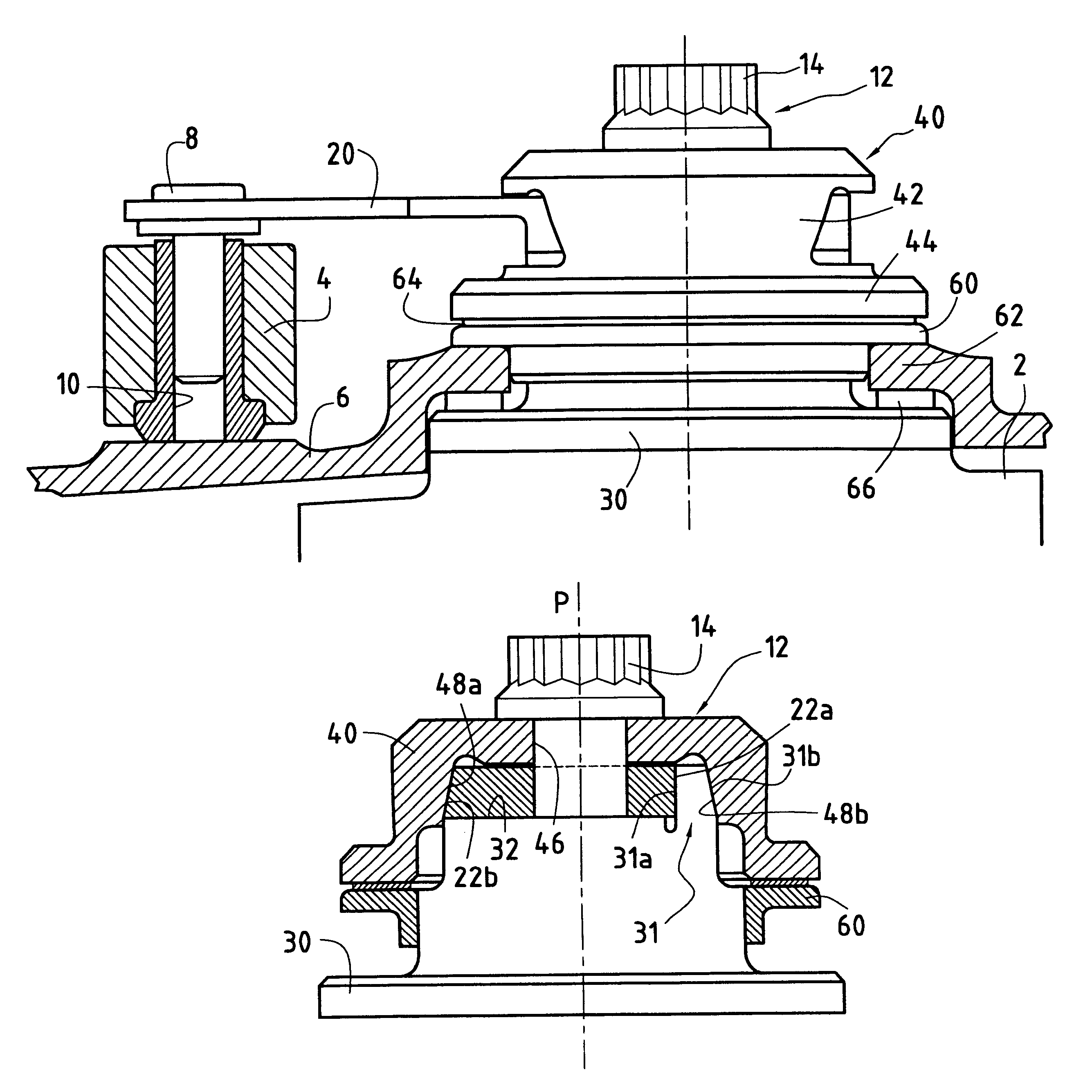
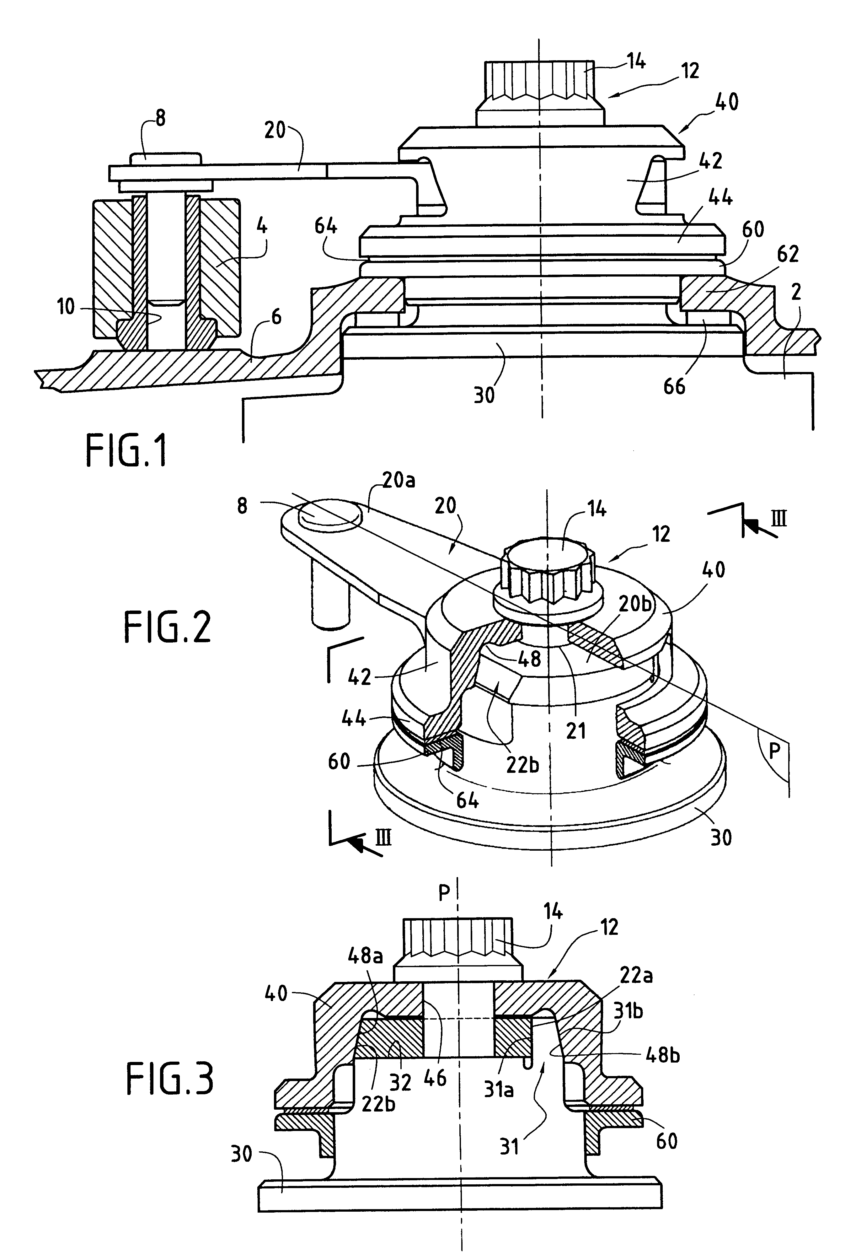
In the invention as shown in FIGS. 2 and 3, the pivot 30 of the vane of the control device has a rigid side portion 31 projecting longitudinally from a top face 32 of the pivot 30 in the vicinity of the edge thereof. This rigid portion is made integrally with the pivot 30, it has a plane inside face 31a that is substantially parallel to the plane P and it has a plane outside face 31b which is inclined relative to the plane P. The plane inside face 31a of the rigid portion may also be slightly inclined relative to the plane P in order to hold the link 20 better on the pivot 30.
The second end 20b of the link 20 presents an orifice 21 in which there is engaged with clearance the screw 14 (or else a threaded rod secured to the vane pivot), and said end bears against the face 32 of the pivot 30. This end 20b of the link has a first side face 22a which is substantially parallel to the longitudinal midplane P of the link and which bears against the plane inside face 31a of the rigid portio...
second embodiment
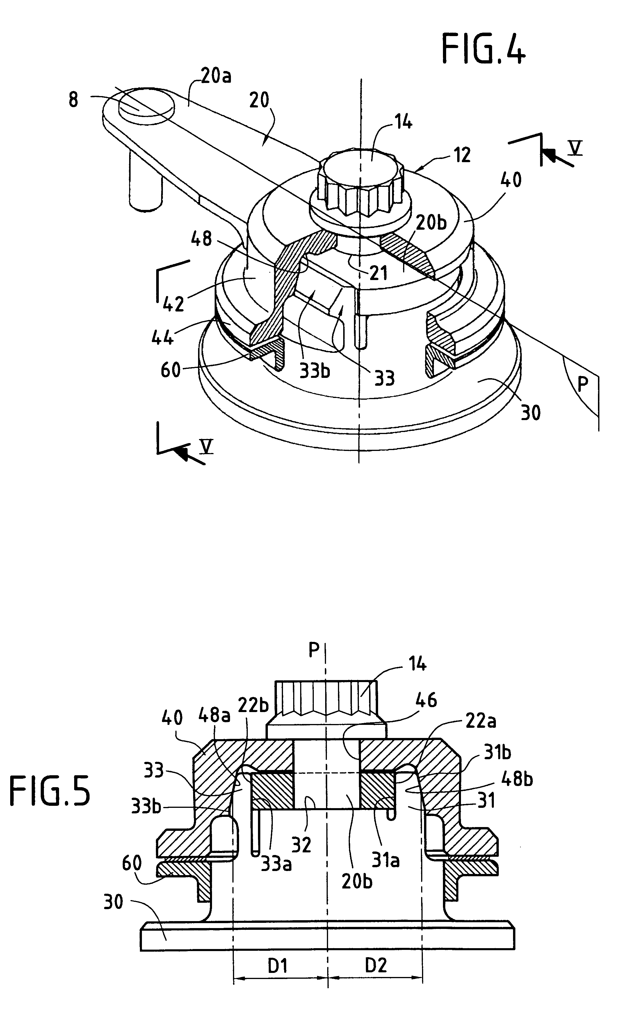
In the invention as shown in FIGS. 4 and 5, the vane pivot 30 of the control device further comprises, compared with the first embodiment described above, a flexible lateral tongue 33 projecting longitudinally from the top face 32 of the pivot 30 and disposed substantially symmetrically to the rigid portion 31 about the longitudinal midplane P of the link. This flexible tongue 33 is made integrally with the pivot 30 and has an inside face 33a substantially parallel to the plane P and an outside face 33b inclined relative to the plane P.
The second end 20b of the link 20 bears against the top face 32 of the pivot 30. The first side face 22a of the end 20b of the link is parallel to the plane P and bears against the inside face 31a of the rigid portion 31, and the second side face 22b of the same end 20b is likewise parallel to the plane P and bears against the inside face 33a of the flexible tongue 33.
The screw 14 is inserted successively through the orifice 46 of the clamping cap, th...
third embodiment
Reference is now made to FIGS. 6 and 7 which show the invention. In this embodiment, the vane pivot 30 of the control device has two slots 34a and 34b that are substantially parallel to the plane P and that are formed between a central block 35 of the pivot 30 and two thin side portions 36a and 36b forming flexible tongues. Each of these thin side portions has a respective outside face 37a or 37b which is inclined relative to the longitudinal midplane P of the link.
The second 20b of the link 20 bears against the top face 32 of the central block 35 of the pivot 30. This end 20b is of channel section having two flanges 24a and 24b engaged in the slots 34a and 34b respectively of the vane pivot 30.
The screw 14 is inserted successively through the orifice 46 of the clamping cap, through the orifice 21 in the second end of the link, and into the orifice formed in the vane pivot. When a screw-and-nut system is used, the threaded rod secured to the vane pivot passes likewise through the or...
PUM
 Abstract
Description
Claims
Application Information
 - R&D
- Intellectual Property
- Life Sciences
- Materials
- Tech Scout
- Unparalleled Data Quality
- Higher Quality Content
- 60% Fewer Hallucinations
Browse by: Latest US Patents, China's latest patents, Technical Efficacy Thesaurus, Application Domain, Technology Topic, Popular Technical Reports.
© 2025 PatSnap. All rights reserved.Legal|Privacy policy|Modern Slavery Act Transparency Statement|Sitemap|About US| Contact US: help@patsnap.com


