Image forming device

a technology of image forming device and carrying belt, which is applied in the direction of electrographic process, recording apparatus, instruments, etc., can solve the problems of not being able to waste the toner, and not being able to make the carrying belt dirty,

Inactive Publication Date: 2003-08-28
OKI ELECTRIC IND CO LTD
View PDF25 Cites 13 Cited by
  • Summary
  • Abstract
  • Description
  • Claims
  • Application Information

AI Technical Summary

Problems solved by technology

However, the conventional tandem-type image forming device has problems to be solved as described below.
As a result, neither the carrying belt is made dirty, nor toner is wastefully consumed.

Method used


Image

  • Image forming device
  • Image forming device
  • Image forming device

Examples


second embodiment

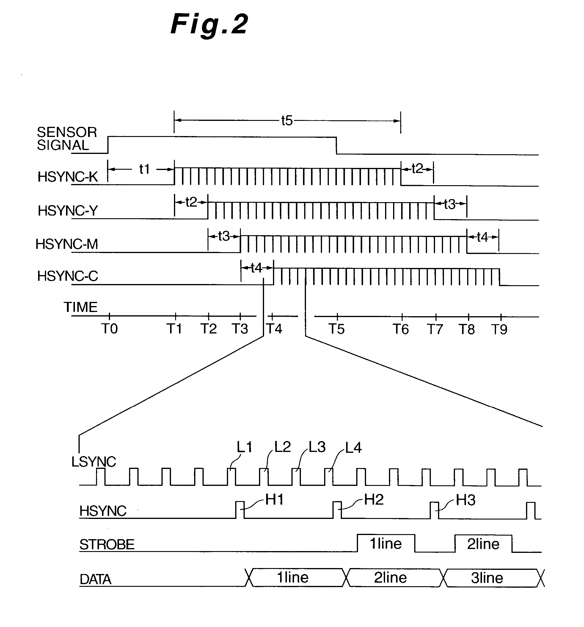
[0178] As described above, in the second embodiment, instead of the exposure start time calculating unit 5 (FIG. 1), the image data feeding start time calculating unit 21 is provided and, instead of the exposure inhibiting time calculating unit 6 (FIG. 1), the blank data feeding time calculating unit 22 is provided. Thus, when a sheet of paper 12 having its length being shorter than its predetermined length, the blank data is transferred by exposure to a surface of the photosensitive drum being equivalent to a portion being not covered by a predetermined length of the paper 12.

[0179] As a result, no image is not transferred to a place being outside the paper, no carrying belt is not made dirty, and no toner is consumed wastefully.

third embodiment

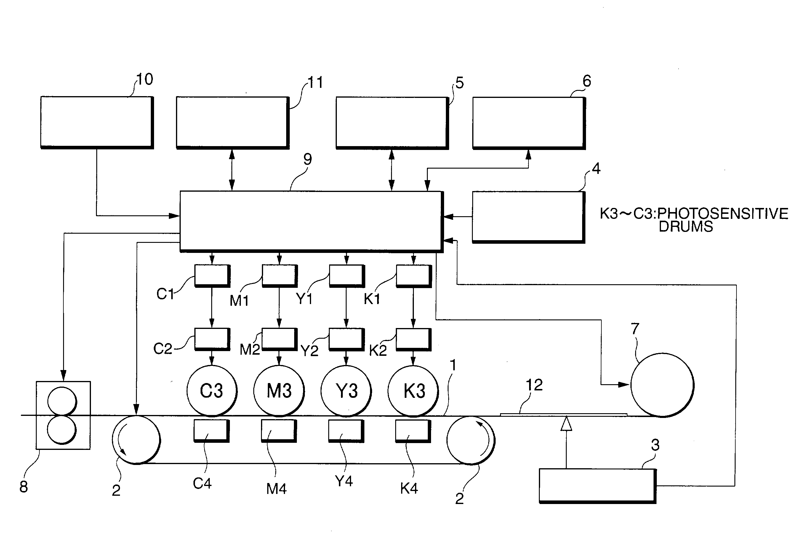
[0180] FIG. 6 is a schematic block diagram showing configurations of an image forming device according to a third embodiment of the present invention. The image forming device of the third embodiment as shown in FIG. 3 includes a carrying belt 1, a carrying roller 2, a paper edge detecting section 3, a device performance storing section 4, a fixing device 8, a clock generator 10, a sub-scanning clock generating unit 11, a page data transfer starting unit 31, a page data transfer time measuring unit 32, a count stopping unit 33, a control section 34, a delay time storing section 35, LED controlling units K1, Y1, M1, and C1, exposure devices K2, Y2, M2, and C2, photosensitive drums K3, Y3, M3, and C3, and transfer devices K4, Y4, M4, and C4.

[0181] Only configurations of the image forming device of the third embodiment of the present invention being different from the first embodiment will be described. Moreover, in the first and second embodiments, the present invention is explained i...

first embodiment

[0185] The control section 34 controls the paper edge detecting section 3 (in the same manner as in the first embodiment), page data transfer starting unit 31, page data transfer time measuring unit 32, and count stopping unit 33 to transfer a desired image for each of the plurality of photosensitive drums and, when having received a sheet of paper having a length being larger than a length of the paper predetermined in advance, controls the count stopping unit 33 and receives an edge detecting signal to re-start counting so that transfer of page data to the paper having pages exceeding a pre-set number of counts is made possible.

[0186] That is, the control sections 34 serves as a CPU to control all portions in the image forming device. The page data transfer starting unit 5 and page data transfer time measuring unit 32, and count stopping unit 33 may be configured as a control program that operates the CPU. It is needless to say that these units 32 and 33 can be configured as an in...


PUM


Abstract

A tandem-type image forming device is provided which includes a plurality of photosensitive drums, a paper edge detecting section to detect a front edge and a rear edge of a sheet of paper, an exposure starting time calculating unit for each of a plurality of photosensitive drums, an exposure inhibiting time calculating unit to inhibit printing, when paper having a length being smaller than a predetermined length of the paper is inserted, on a portion being shorter than preset paper, and a control section to control an entire image forming device. By configuring as above, the tandem-type image forming device can be realized by using only one paper edge detecting sensor and only one detecting circuit. Even when paper having a length being smaller than a preset length of the paper is inserted, no transfer of an image to a place outside of the paper, that is, to a carrying belt occurs.

Description

[0001] 1. Field of the Invention[0002] The present invention relates to a tandem-type image forming device.[0003] 2. Description of the Related Art[0004] In a conventional tandem-type image forming device, generally, a method is employed in which a plurality of image forming units are arranged in a paper carrying direction. In such the method, an edge of a sheet of paper is detected for every image forming unit. Print timing is determined and provided for each photosensitive drum based on a relation of the time of detecting an edge of a sheet of paper, a position of attaching each of image forming units, and a carrying speed of the sheet of paper and printing is initiated sequentially to transfer an image to a sheet of paper.[0005] However, the conventional tandem-type image forming device has problems to be solved as described below. That is, each of the image forming units has to be provided with a paper edge detecting sensor and a detecting circuit. Moreover, if paper being short...

Claims


Application Information

Patent Timeline
Patent Type & Authority Applications(United States)
IPC IPC(8): B41J11/42B41J29/38B41J13/00G03G15/01G03G21/00G03G21/14H04N1/00
CPCB41J13/0054B41J11/42
Inventor NAKASENDO, TAKASHI
Owner OKI ELECTRIC IND CO LTD
Why Eureka
Try Eureka