Method for binding books and a cutter therefor

Inactive Publication Date: 2003-09-11
YEW LAI CHEAN
View PDF19 Cites 4 Cited by
  • Summary
  • Abstract
  • Description
  • Claims
  • Application Information

AI Technical Summary

Benefits of technology

0024] Since the flaps are along the spine, they act as hinges for each pages, allowing the books to be opened in a flat manner or folded backwards with minimum lever pressure on th

Problems solved by technology

It is known that books bound by the conventional perfect binding have extreme difficulties in withstanding rough handling.
Books that use heavily coated papers are most likely to break apart with repeated handling.
The problem of the perfect binding lies i

Method used


Image

  • Method for binding books and a cutter therefor
  • Method for binding books and a cutter therefor
  • Method for binding books and a cutter therefor

Examples


Embodiment Construction

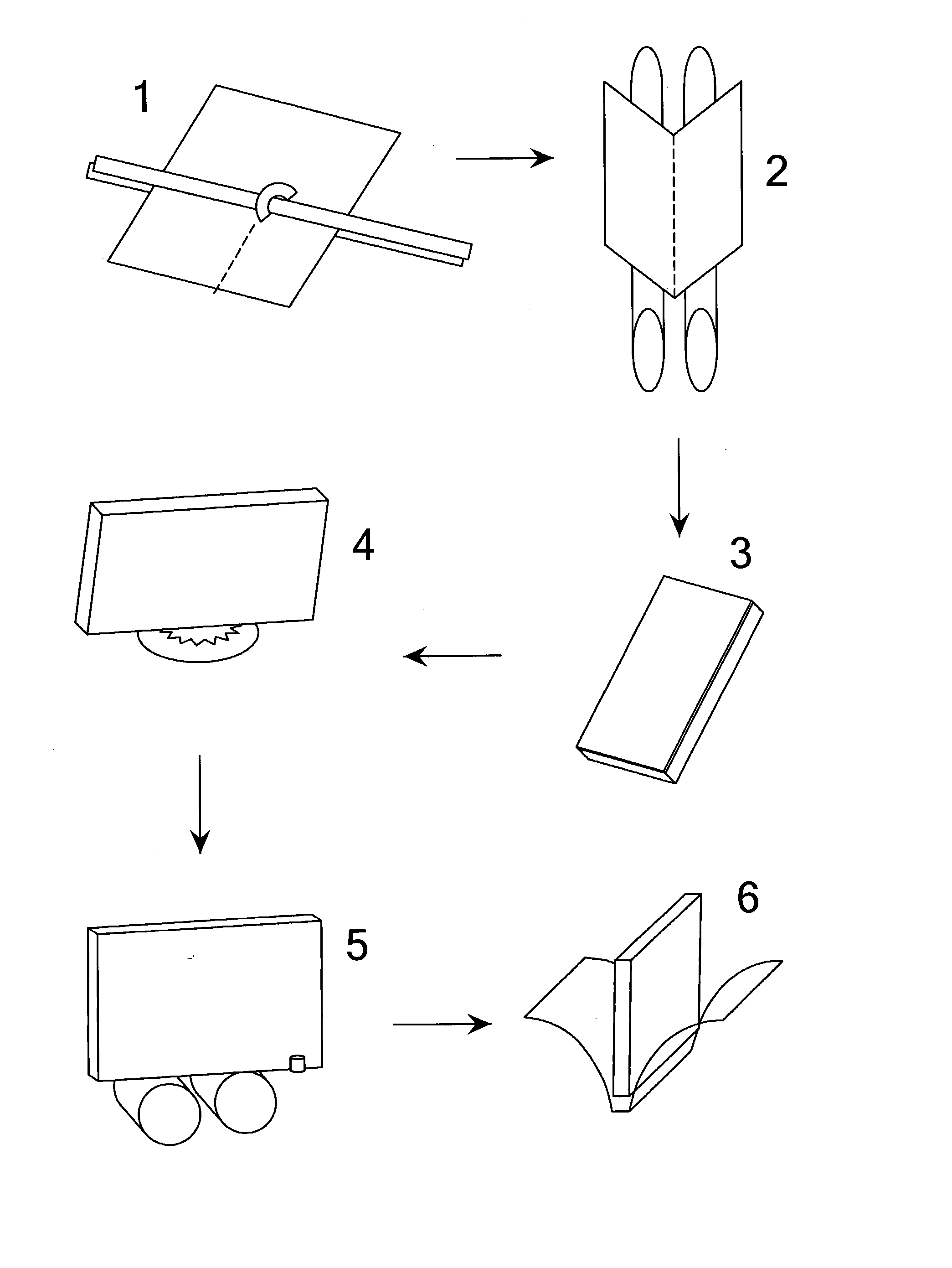
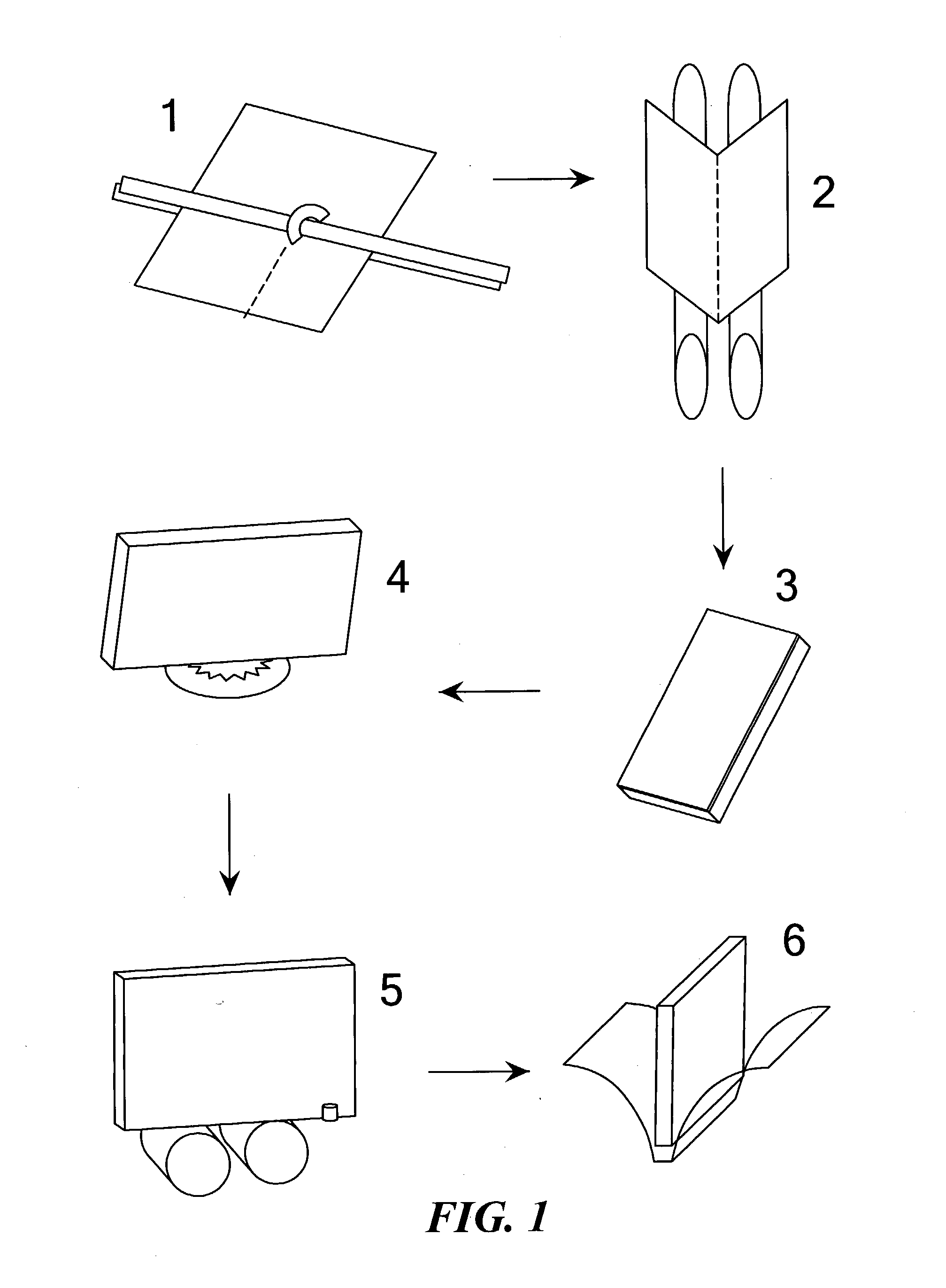
[0032] FIG. 1 shows the different steps in the perfect binding system. Whether in the Web printing process or the sheet printing system, the large printed sheets will need to be folded to the final book size before the actual binding process. In the conventional system, any signature that is designed to be perfect bound is ideally perforated at the spine as shown in 1, solely to reduce creases or wrinkles forming on the inside page of the multi-layered folded signature. Once the signature is perforated, it will pass to the folding section to be folded as shown in 2. In forming the book text in 3, several different folded signatures are compiled together. This book text is now in the perfect binding process.

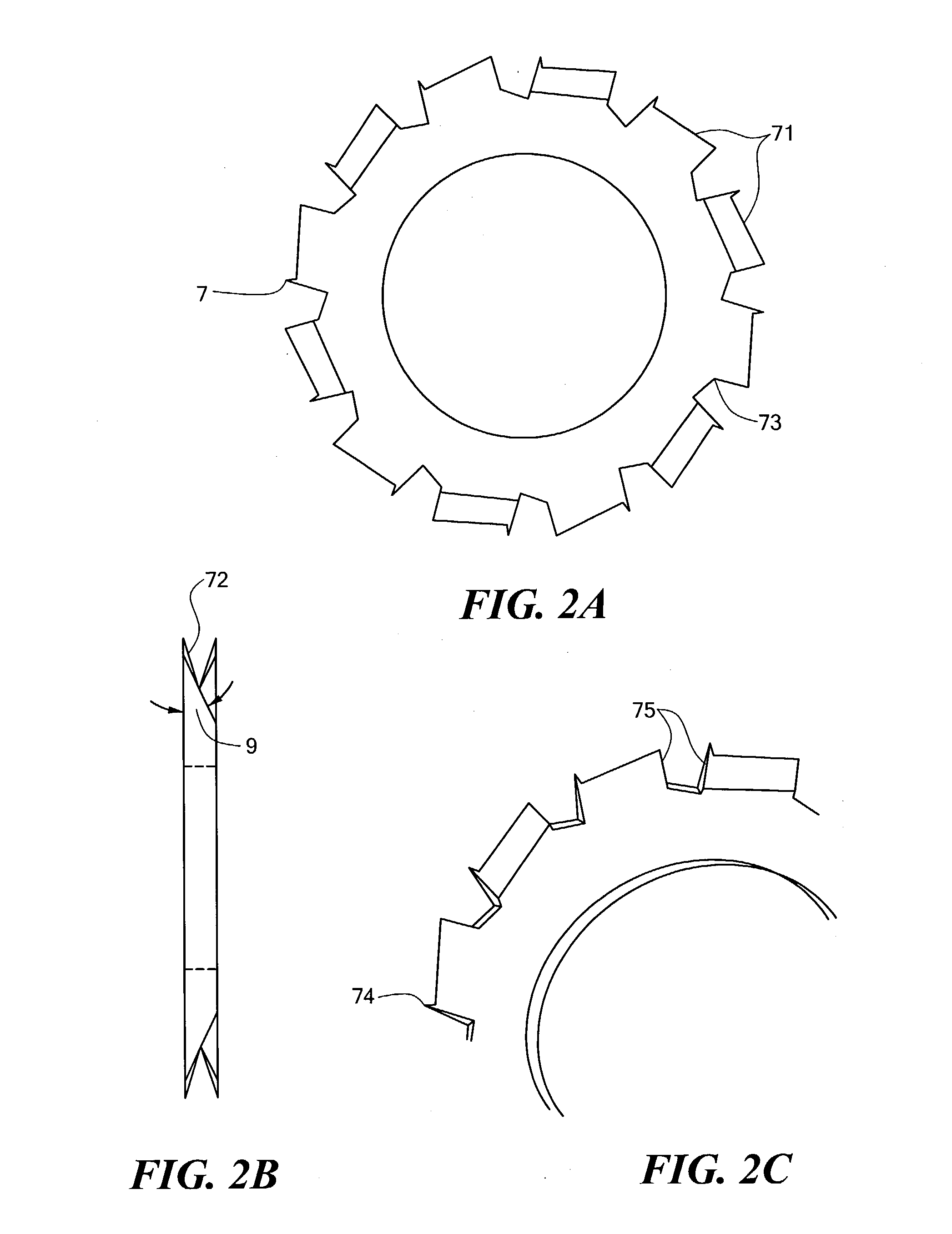
[0033] In the perfect binding machine, the book text, as shown in 4, is passed through a milling station where the spine of the book text is milled laterally into a rough flat base. After the milling process, the book text will, in the same machine, passed through the hot melt sta...


PUM


Abstract

There is disclosed a new method for binding a book and a new cutter therefore. The method comprises perforating a plurality of signatures along a spine, bending the plurality of signatures along the spine, compiling the plurality of signatures into a book text and applying adhesive to the book text. A cutter for making perforation adapted for the method is also disclosed.

Description

1.0 TECHNICAL FIELD OF THE INVENTION[0001] The present invention relates generally to a method for binding books, especially to a method for making alternate flaps along spine of a multi-layered signature, and a new perforating cutter therefor. These alternating flaps form the basis of a new method in the binding process, called the "LOCK SYSTEM".2.0 BACKGROUND OF THE INVENTION[0002] It is known that books bound by the conventional perfect binding have extreme difficulties in withstanding rough handling. Books that use heavily coated papers are most likely to break apart with repeated handling. These problems have been overcome by the relatively more expensive thread sewing in the spine.[0003] The problem of the perfect binding lies in the preparatory steps on the signature spine. Conventionally, a collection of multi-layered signatures that forms a book, bound for perfect binding using hot-melt adhesive, passes through a milling station in the perfect binding machine. The milling s...

Claims


Application Information

Patent Timeline
IPC IPC(8): B42C5/04
CPCB42C5/04
Inventor YEW, LAI CHEAN
Owner YEW LAI CHEAN
Why Eureka
Try Eureka