
Mounting system for supporting objects

a technology for mounting systems and supporting objects, which is applied in the direction of heat collector mounting/support, snow traps, lighting and heating apparatus, etc., can solve the problems of reducing the structural integrity of the mounting system, the risk of lag bolts being drills, and the satellite dish and solar panel

Inactive Publication Date: 2003-09-25
ULLMAN STANLEY A
View PDF7 Cites 141 Cited by
  • Summary
  • Abstract
  • Description
  • Claims
  • Application Information

AI Technical Summary

Problems solved by technology

However, a problem exists for other objects such as satellite dishes and solar panels, which can, in certain windy conditions, be lifted off the mounting equipment to which they are attached because the force of the wind applied against the surface area on the side or underside of the object creates an uplift condition which is greater than the attachment strength of the mounting equipment.
One of the problems with present installations is the fact that more than one lag bolt or other type of fastening bolt is required for each mounting plate that is fastened to the roof.
The risk is high that some of the lag bolts will drill at an angle other than perpendicular to the roof rafter.
The severity of the angle and the trajectory of the lag bolt penetration into the rafter could cause the rafter to split; further reducing the structural integrity of the mounting system.
The Merrin design, as well as similar prior art, have a common design limitation.
Also, because of the floor flange design, it would not permit industry standard flashing to install flat on the roof; primarily due to the base flashing circumference interfering with the height of the floor flange.
A mounting system based upon the Merrin patent, while appropriate for roof mounting of heavy objects such as air conditioners, is not practical for use with lighter objects such as solar panels or satellite dishes.
Further, Merrin views rafter attachment as a limitation and therefore teaches away from using rafters for structural support.
Therefore, Merrin teaches attachment to the roof decking which generally consists of only 1 / 2 "plywood or composite sheeting; either of which does not provide the strength of a bolt mounted to a rafter in an uplift condition.
Consequently, fewer rafters are available to secure a given length of support rail to a commercial roof than for a residential roof.
Unfortunately, doing either dramatically increases material and labor costs.
Although this method is adequate for residential rooftops, use upon commercial rooftops, particularly when only two support beams are available for attachment, creates a "hinge point" which can cause the support rail to undesirably move when there is a change in load.
This situation is not a problem when the span between roof attachments is short but does become a problem with longer lengths of support rails.
The principal drawback to this design is that the bolt head creates a "hinge point" which can permit the channel member to rotate about this hinge point relative to the vertical support member.
This situation can occur particularly when additional load is applied upon the structure.
Another drawback to the bolt head attachment design is that the semi-closed groove utilized prevents water from being able to freely drain from the support rail at the moment of structural attachment.
Also, the roof top is a polluted environment and in time dirt and other debris will eventually make there way into the semi-closed groove.
The freezing water, if trapped in the restricted groove will expand, stressing the metal which may cause splitting or structural failure of the support rail at the moment of structural attachment.
The bolt head attachment described above offers no structural strength particularly to resist side to side movement.
Again, the vertical post or support could collapse under load unless fitted with additional bracing.
Again, this creates a structural hinge point which cannot reduce or minimize deflection along the span of the support rail or vertical support.
Under these load conditions, the support rail and hinged vertical support member will simply torque or twist causing excess deflection of the support rail and / or possible failure.
Another problem is that in some designs, the vertical support legs are off center relative to the weight of the entire mounting structure.
If the vertical member were to shift because of the mounting structure load or because of high winds or excess snow upon said structure, buckling of the entire mounting structure could occur leading to collapse.
A final issue with installing mounting structures upon a roof top is that the rooftop may not be level.
Installing the same mounting plates across a roof which has an uneven surface could undesirably lead to a solar panel assembly installation having its support members stressed or resulting in a pulling on the support beams to achieve alignment when attaching to a base mount.

Method used


Image

  • Mounting system for supporting objects
  • Mounting system for supporting objects
  • Mounting system for supporting objects

Examples


second example

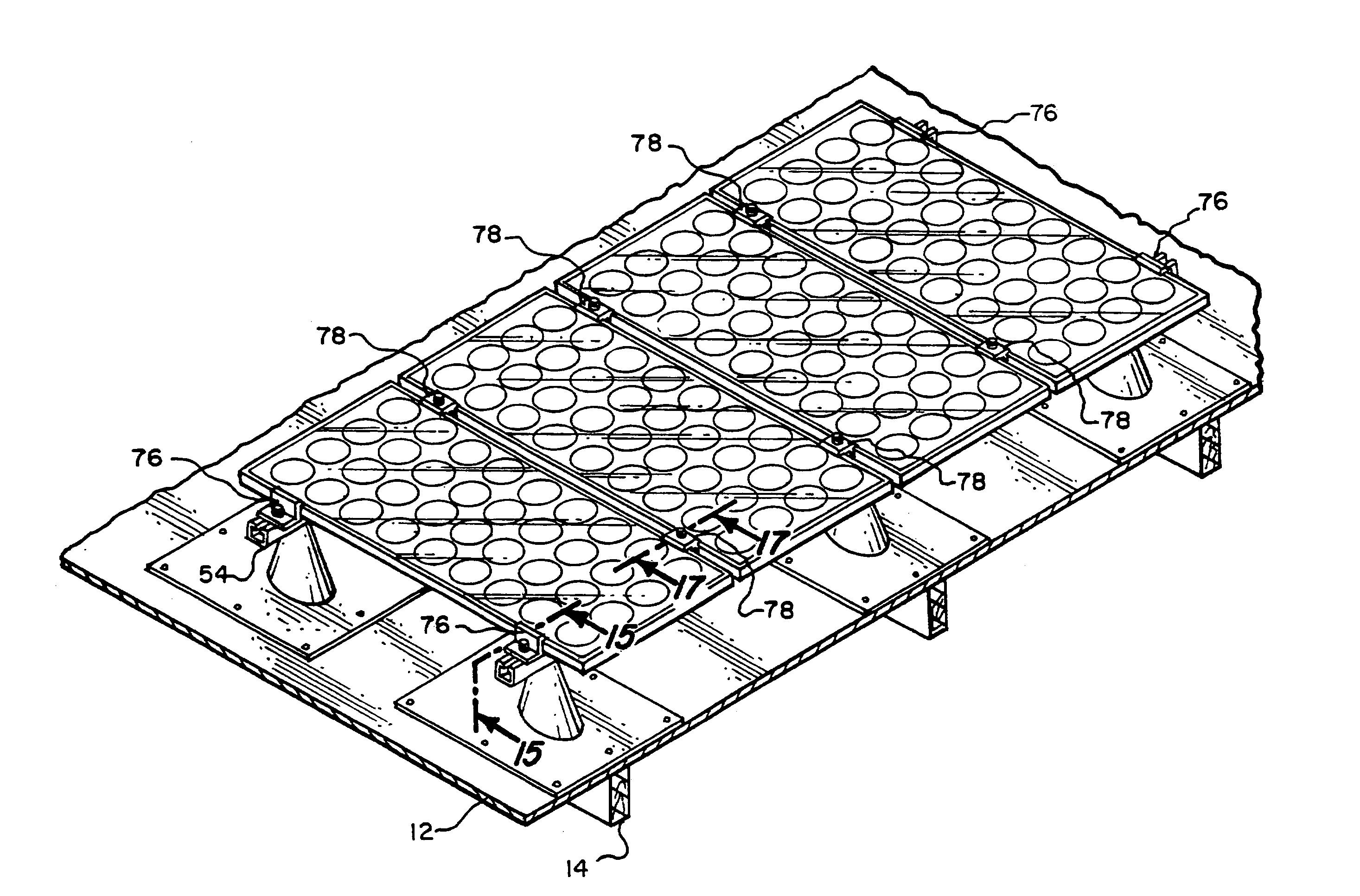
[0040] In a second example, the mounting system, instead of being fastened to a new roof rafter for support, is operatively fastened either: a) upon existing roofs or framework; or, b) over pipe supports or other support systems not necessarily located upon a roof. Here, the roof mount referred to earlier is not utilized although the other features described in paragraphs 2, 3, and 4 above pertain. For this example, the roof mount is replaced as the means to fasten the mounting system with an alternative means such as that described in U.S. Pat. No. 5,746,029 issued to Ullman and which is herein incorporated by reference.

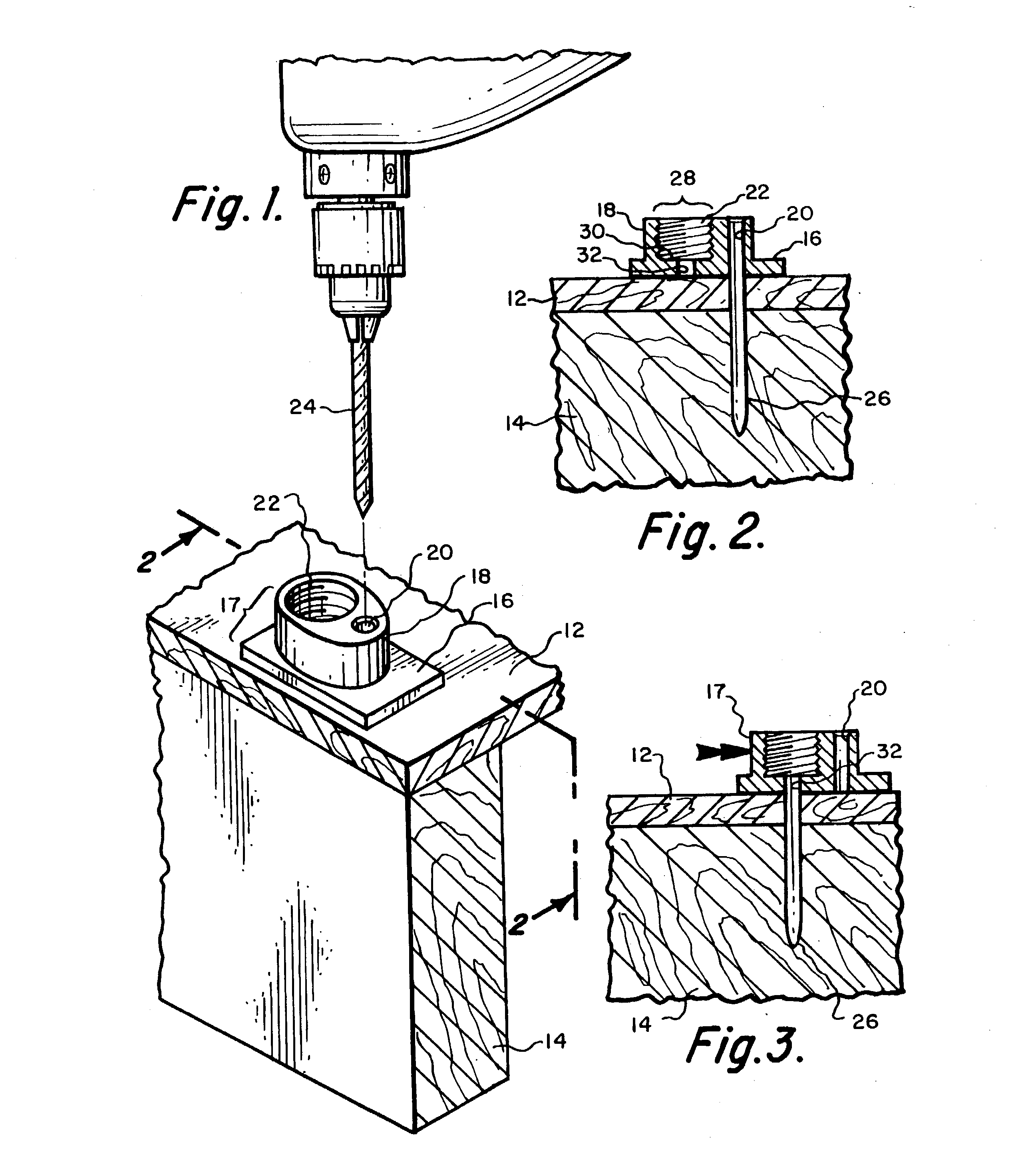
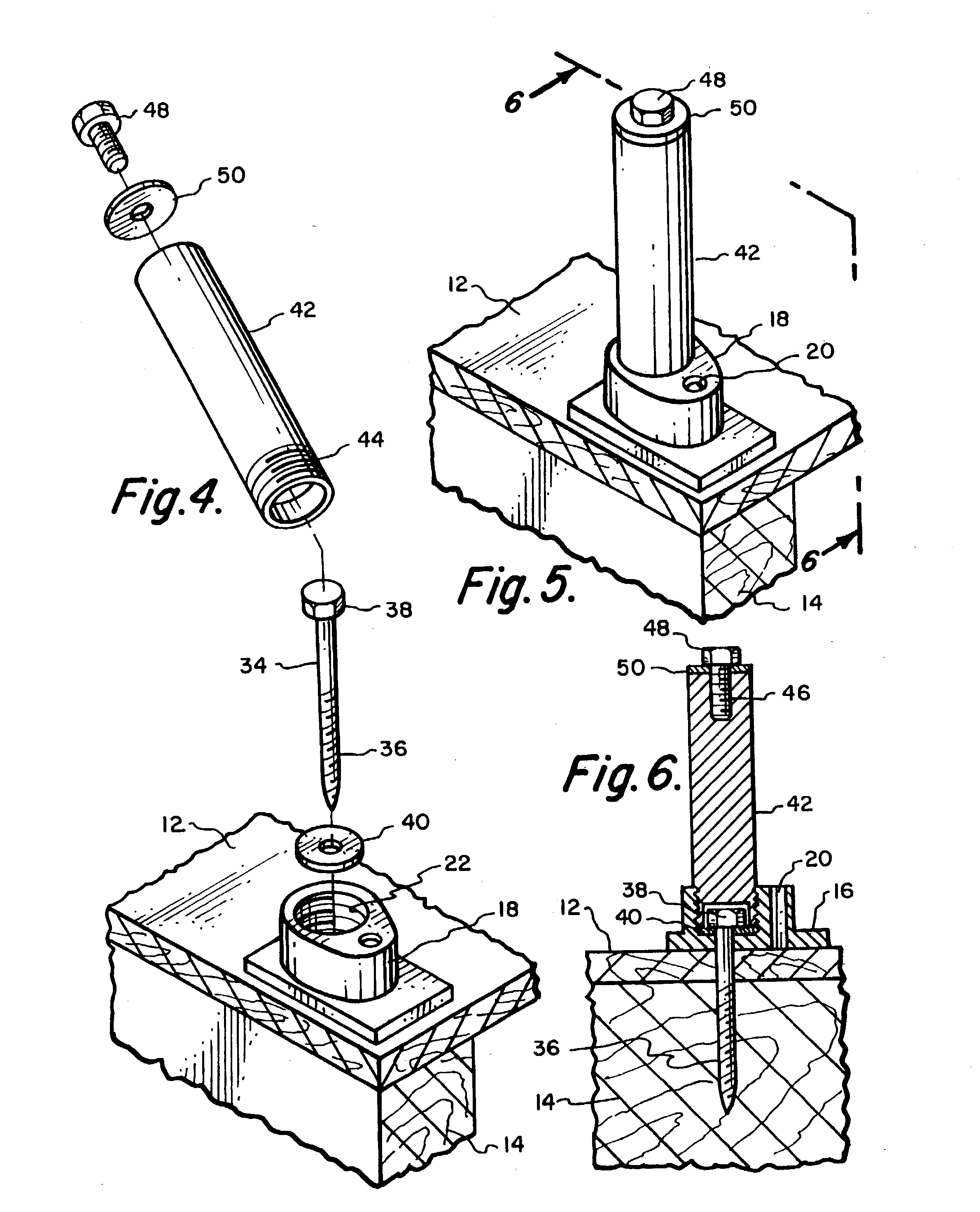
[0041] Roof Mount (For Example 1)

[0042] In order to utilize my mounting system, a roof mount must first be fastened to a rafter. The roof mount can be manufactured from any material commonly used in the building trade to support objects upon a roof. Preferably, the mount is machined from aluminum and comprises a threaded cavity with an insertion opening for threadab...


PUM


Abstract

A new mounting system for elevating and supporting objects such as solar panels and satellite dishes either upon the roofs of commercial buildings. The mounting system utilizes a modified "C" channel having a plurality of longitudinal grooves for engaging mating flanges. The purpose of this equipment is to provide a rigid, stable platform for mounting equipment upon commercial buildings which have rafter spacing much greater than for residential roofs.

Description

CLAIM OF PRIORITY[0001] This is a continuation-in-part application that claims the benefit of U.S. patent application bearing Ser. No. 10 / 104,131 filed Mar. 21, 2002 which claims the benefit of U.S. patent application bearing Ser. No. 09 / 758,407 filed Jan. 10, 2001 (now U.S. Pat. No. 6,360,491) which claimed priority to U.S. Provisional Application bearing serial No. 60 / 176,126 filed Jan. 14, 2000.[0002] The present invention relates to the building industry and specifically to mounting equipment and a method for supporting an object over a roof or above ground.BACKGROUND OF INVENTION[0003] This background incorporates the disclosure from the previous two utility applications referenced above. The additional background information pertaining to the new matter presented in this application is identified below.[0004] Mounting equipment sometimes referred to herein as a mounting system, is used to attach objects such as solar panels including photovoltaic (PV) modules and solar pool he...

Claims


Application Information

Patent Timeline
Patent Type & Authority Applications(United States)
IPC IPC(8): E04D13/12F24J2/52H01L31/048
CPCE04D13/12F24J2/5205F24J2/5233F24J2/5245F24J2/5258H02S20/23F24J2002/5486Y02B10/12Y02B10/20Y02E10/47F24J2002/4669F24S25/61F24S2025/6008F24S25/13F24S2030/16F24S25/33F24S25/636F24S2025/6006Y02E10/50Y02B10/10
Inventor ULLMAN, STANLEY A.
Owner ULLMAN STANLEY A
Learn More