
Drum brake device with an automatic shoe clearance adjustment apparatus

a drum brake and automatic adjustment technology, which is applied in the direction of mechanically actuated drum brakes, slack adjusters, brake elements, etc., can solve the problems of dragging problems, delay in the braking effect, and give the driver a disconcerting brake feeling

Inactive Publication Date: 2003-10-02
NISSHINBO IND INC
View PDF13 Cites 18 Cited by
  • Summary
  • Abstract
  • Description
  • Claims
  • Application Information

AI Technical Summary

Benefits of technology

[0022] The drum brake as structured above, arranging (positioning) the thermo-sensitive member at the free end side of the lever allows setting an opening force (force to move two legs of the thermo-sensitive member apart from each other) lower to the magnitude apportioned by the lever-ratio at the position of the thermo-sensitive member, thereby enabling a smaller design for the thermo-sensitive member, thus minimizing material and thereby reducing the cost thereof.

Problems solved by technology

While the drum brake is expanding, if the automatic shoe clearance adjustment apparatus is configured such that an automatic shoe clearance adjustment functions to adjust the shoe-to-drum clearance, temporarily enlarged because of the brake drum expansion, when the brake drum is cooled and the temperature thereof decreases, this shrinks the brake drum and causes it to return to its normal state, the shoe-to-drum clearance already adjusted during the temporary brake drum expansion remains the same and this can be considered an over-adjustment and may possibly cause a dragging problem.
If the shoe-to-drum clearance in a normal state (not in a use under a predetermined high-temperature) is preset to be wider in order to avoid dragging, a shoe clearance over-adjustment could be prevented, but strokes, such as a brake pedal stroke and a brake lever stroke, become larger and this then causes a delay in the braking effect and gives the driver a disconcerting brake feeling.
Accordingly, weight of the thermo-sensitive member inevitably increases, thereby increasing the cost thereof.

Method used


Image

  • Drum brake device with an automatic shoe clearance adjustment apparatus
  • Drum brake device with an automatic shoe clearance adjustment apparatus
  • Drum brake device with an automatic shoe clearance adjustment apparatus

Examples


Embodiment Construction

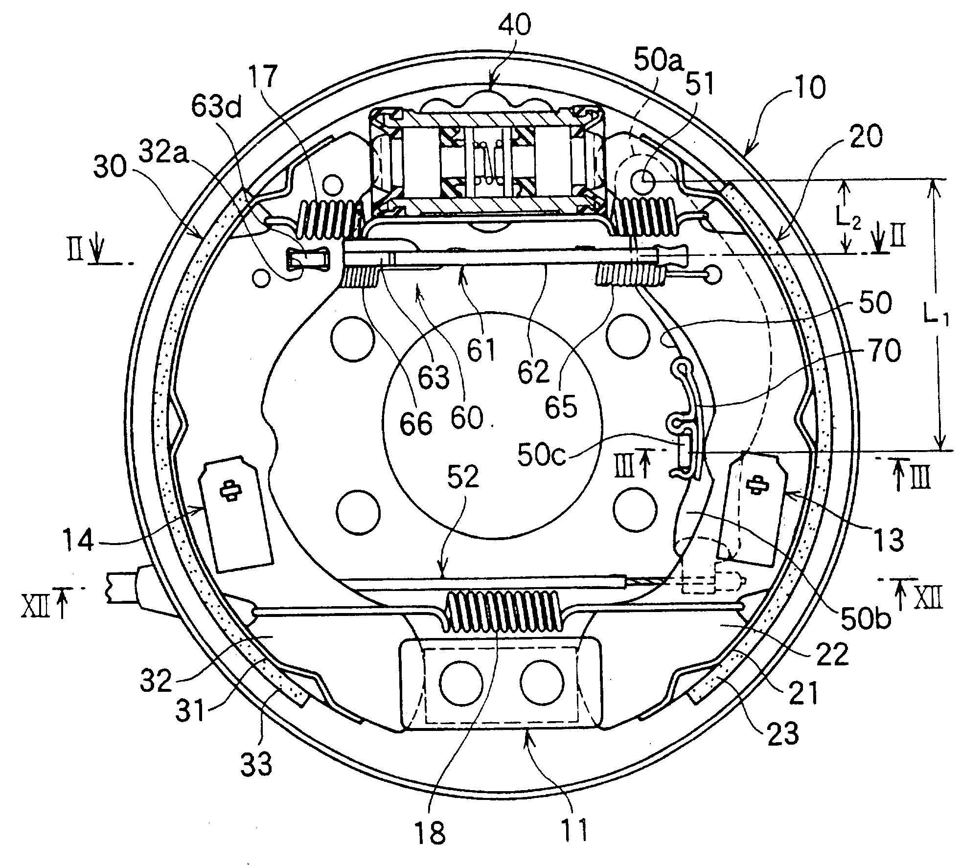
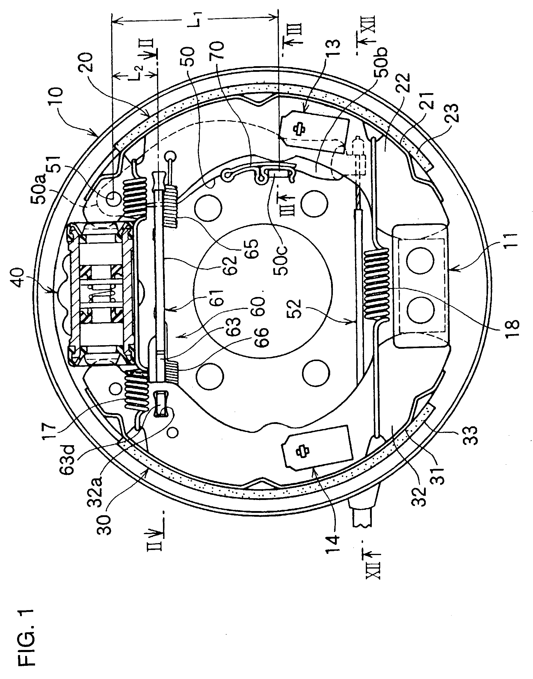
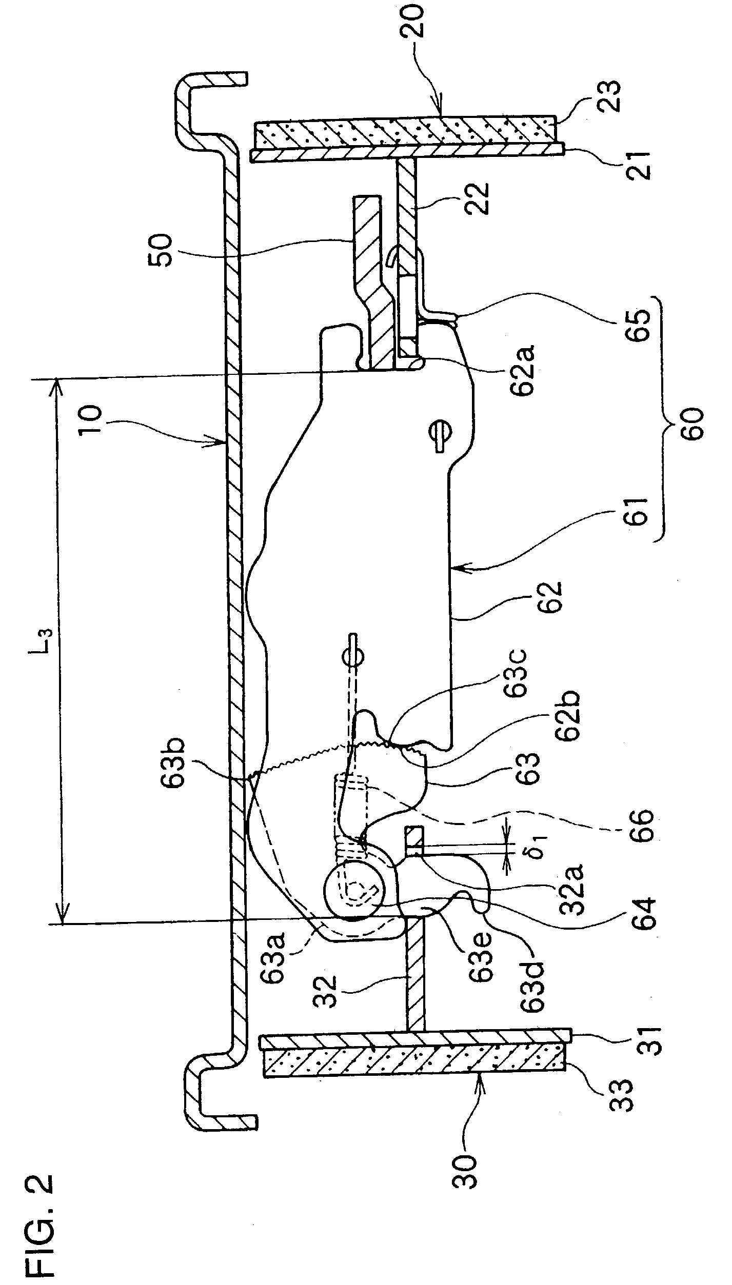
will be explained with reference to FIGS. 1-4.

[0040] A pair of facing brake shoes 20, 30, each makes a T-shape in cross-section as a shoe rim 21 and a shoe web 22 combined together while a shoe rim 31 and a shoe web 32 combined together, and linings 23, 33 are affixed on peripheral surfaces of the shoe rim 23, 33 respectively.

[0041] Every one of the brake shoes 20, 30 is slidably supported on a back plate 10 which is fixed on a stationary portion of a vehicle by means of shoe-hold mechanisms 13, 14.

[0042] Upper adjacent ends of the shoe webs 22, 32 functionally engage with a wheel cylinder 40 fixed on the back plate 10, and lower adjacent ends of the shoe webs 22, 32 are supported by an anchor block 11 fixed on the back plate 10.

[0043] A brake lever 50 as a parking brake actuator is superposed on the shoe web 22 of the right brake shoe 20 as shown in FIG. 1.

[0044] The brake lever 50 is designed to be a plate-like member and such that a proximal portion 50a of the brake lever 50 is p...


PUM


Abstract

A drum brake device prevents shoe clearance over-adjustment by means of a thermo-sensitive member with a lower leg opening force and provides a smaller thermo-sensitive member with a lower cost. A portion between both ends of the brake lever (50) in a direction of crossing the shoe return inhibitor (61) engages with one end of the shoe return inhibitor (61) automatically restricting the return position of the pair of brake shoes (20) and (30); the proximate portion (50a) of the brake lever (50) is pivotally supported on the brake shoe (20); and the free end (50b) side of the brake lever (50) is supported at the brake shoe (20) via the thermo-sensitive member (70).

Description

[0001] 1. Field of the Invention[0002] This invention relates to a drum brake device with an automatic shoe clearance adjustment apparatus, and, more particularly, to a shoe clearance over-adjustment prevention means which suspends automatic shoe clearance adjustment when the temperature within the brake increases and exceeds a predetermined range.[0003] 2. Description of Related Art[0004] Generally, a drum brake has an automatic shoe clearance adjustment apparatus compensate wear of the brake shoe lining in order to maintain a certain shoe-to-drum clearance.[0005] If the drum brake is repeatedly applied, for example, where if a vehicle is driving down a long downward slope, the temperature of the brake drum increases and thereby expanding the brake drum to cause an apparent shoe-to-drum clearance enlargement, i.e., a temporary enlargement of the shoe-to-drum clearance to the extent of brake drum expansion.[0006] While the drum brake is expanding, if the automatic shoe clearance adj...

Claims


Application Information

Patent Timeline
Patent Type & Authority Applications(United States)
IPC IPC(8): F16D51/22F16D65/40F16D65/58
CPCF16D65/58F16D65/546
Inventor IKEDA, TAKASHI
Owner NISSHINBO IND INC
Learn More