Apparatus and methods for interfacing with remote addressing systems

Inactive Publication Date: 2003-10-02
ELLENBY JOHN +3
View PDF40 Cites 87 Cited by
  • Summary
  • Abstract
  • Description
  • Claims
  • Application Information

AI Technical Summary

Problems solved by technology

However, displays taught there do not provide for changes with regard to available functionality which might depend upon the objects being addressed.
While the systems and inventions of the art are designed to achieve particular goals and objectives, some of those being no less than remarkable, these inventions have limitations which prevent their use in new ways now possible.

Method used


Image

  • Apparatus and methods for interfacing with remote addressing systems
  • Apparatus and methods for interfacing with remote addressing systems
  • Apparatus and methods for interfacing with remote addressing systems

Examples


Embodiment Construction

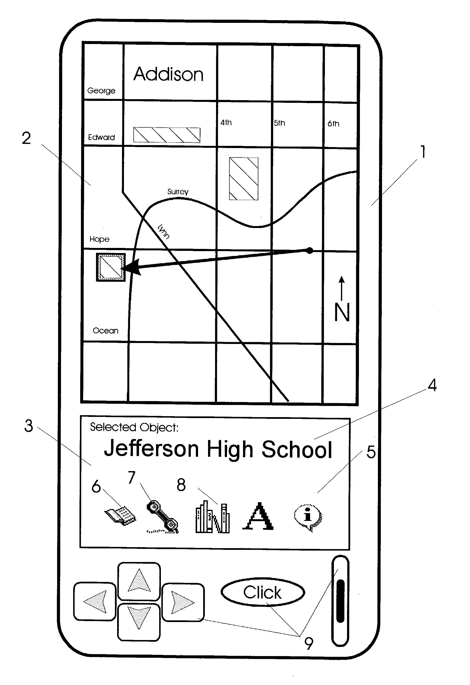
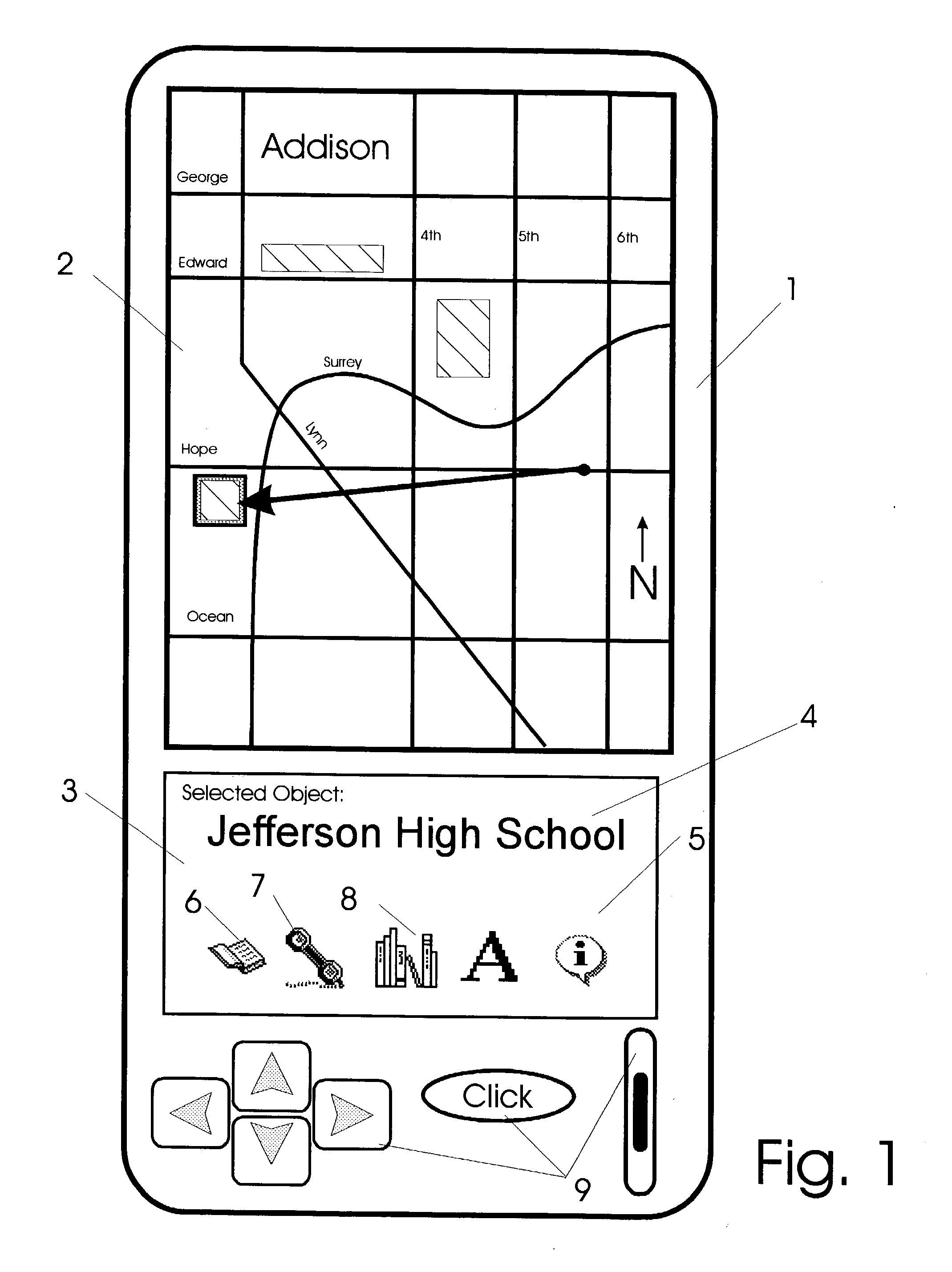
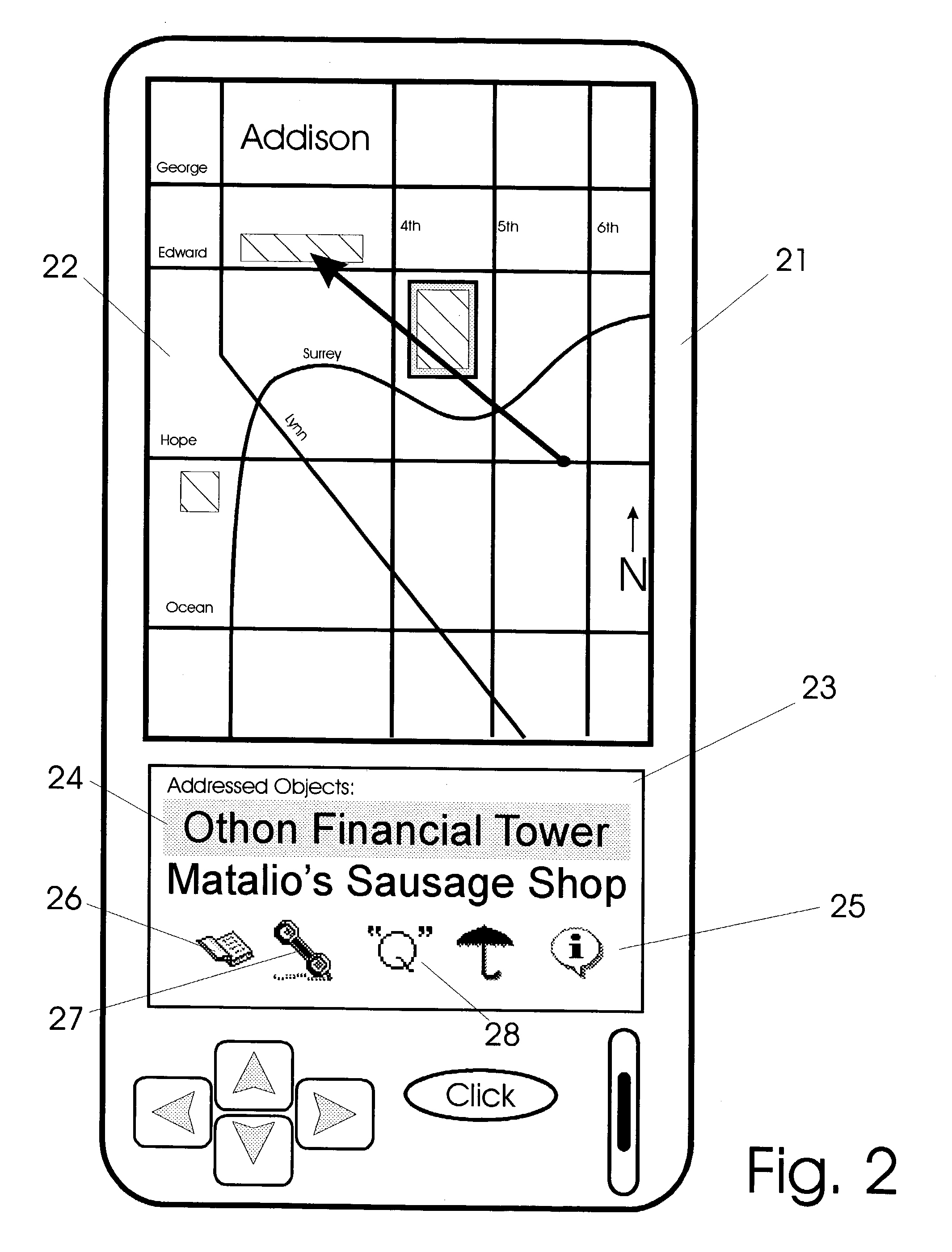
[0072] In accordance with each of the preferred embodiments of the invention, systems for remote addressing of objects are provided. It will be appreciated that each of the embodiments described include both apparatus and methods and that the apparatus and method of one preferred embodiment may be different than the apparatus and method of another embodiment.

[0073] Systems of the invention may be used to address objects from remote locations. As is readily appreciated in view of the detailed disclosures mentioned above, a user may simply point a device of the invention towards an object to address it. A computer determines in real-time which objects are being addressed by comparing object descriptors which are stored in a database with an instant pointing vector defined with respect to a point reference and direction reference of a mobile unit. In the case where a plurality of objects are simultaneously being addressed, a default mechanism causes one of the plurality to be a `select...


PUM


Abstract

Devices for remotely addressing objects via pointing action are provided with graphical user interfaces. In response to an object being addressed, a computer device and software provide graphical user interfaces which relates to objects being addressed. As different types of objects are addressed, user interfaces provided change in form and function to agree with the type of category of object being addressed at that instant. Devices have position and attitude determining facility in communication with a computer having prerecorded data. The data includes information relating to object types and corresponding graphical user interfaces.

Description

[0001] 1. Field[0002] The following invention disclosure is generally concerned with computer interfaces; it is more specifically concerned with presenting toolbar icon interfaces to provide access to computer functionality in response to address actions made by a user.[0003] 2. Prior Art[0004] Co-pending applications having U.S. Ser. Nos. 09 / 110,572, 09 / 384,469, 09 / 510,889, 09 / 615,923, 09 / 805,421 and 09 / 163,746, are applications which relate to the present invention. Those disclosures, in their entirety, are incorporated herein by reference.[0005] In addition, the entire text of seven US Patents by some of the same inventors are also incorporated herein by reference for a more perfect understanding of these inventions, including: U.S. Pat. Nos. 6,173,239; 5,815,411; 5,625,765; 5,682,332; 6,064,398; 6,037,936; and 5,742,521.[0006] With reference to FIG. 10 of the U.S. application Ser. No. 09 / 110,572 application, one will appreciate how a person using devices of that invention can po...

Claims


Application Information

Patent Timeline
IPC IPC(8): G01C21/20G06F1/16G06F3/038
CPCG06F2200/1637G01C21/20G06F1/1626G06F3/0481G06F1/1694G06F3/038G06F1/169G06F16/29G06F16/9537H04M1/72457H04M1/72454H04L67/131
Inventor ELLENBY, JOHNELLENBY, THOMASELLENBY, PETERPAGE, JOSEPH
Owner ELLENBY JOHN
Why Eureka
Try Eureka