Bionic Muscle

a technology of muscle and muscle, applied in the field of biomechanical engineering, can solve the problems of large device mass, complex control system, and current approach, and achieve the effect of reducing the size of the devi

Active Publication Date: 2016-06-30
CLARUS TECH
View PDF15 Cites 4 Cited by
  • Summary
  • Abstract
  • Description
  • Claims
  • Application Information

AI Technical Summary

Benefits of technology

[0034]The bionic muscle mass as specified above may have the bionic muscle cells within a bionic muscle fiber are, in their non-energized state, separated one from another along their magneti

Problems solved by technology

As a consequence, in order to achieve the necessary performance, these devices are bulky, require a sizeable power supply and are generally only capable of providing force between two anchor points along a straight line.
Furthermore current approaches typically require complex control systems to first sense and then control the amount of movement require

Method used


Image

  • Bionic Muscle
  • Bionic Muscle
  • Bionic Muscle

Examples


Embodiment Construction

[0050]After considering this description it is apparent to one skilled in the art how the invention is implemented in various alternative embodiments and alternative applications. However, although various embodiments of the present invention is described herein, it is understood that these embodiments are presented by way of example only, and not limitation. As such, this description of various alternative embodiments should not be construed to limit the scope or breadth of the present invention. Furthermore, statements of advantages or other aspects apply to specific exemplary embodiments, and not necessarily to all embodiments covered by the claims.

[0051]Throughout the description and the claims of this specification the word “comprise” and variations of the word, such as “comprising” and “comprises” is not intended to exclude other additives, components, integers or steps.

[0052]Reference throughout this specification to “one embodiment” or “an embodiment” means that a particular...


PUM


Abstract

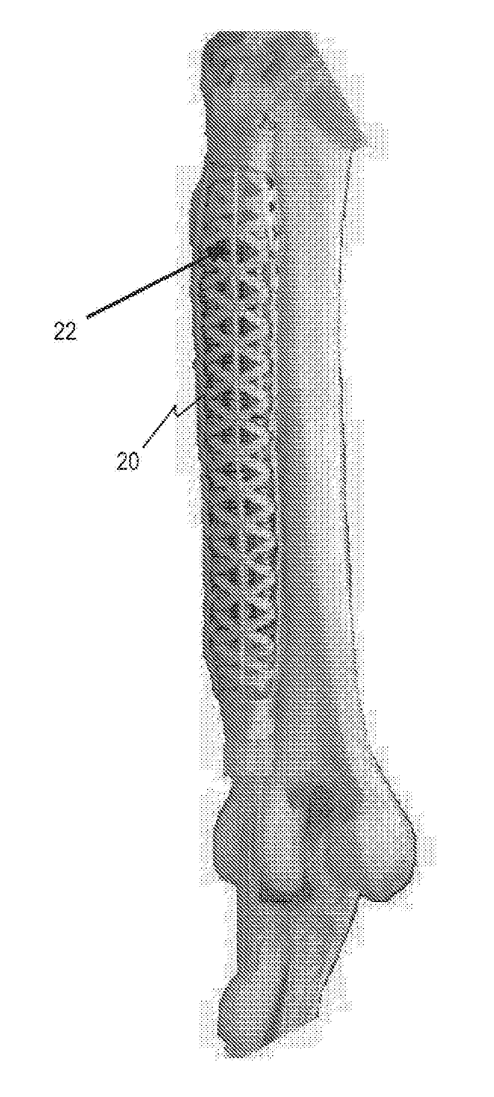
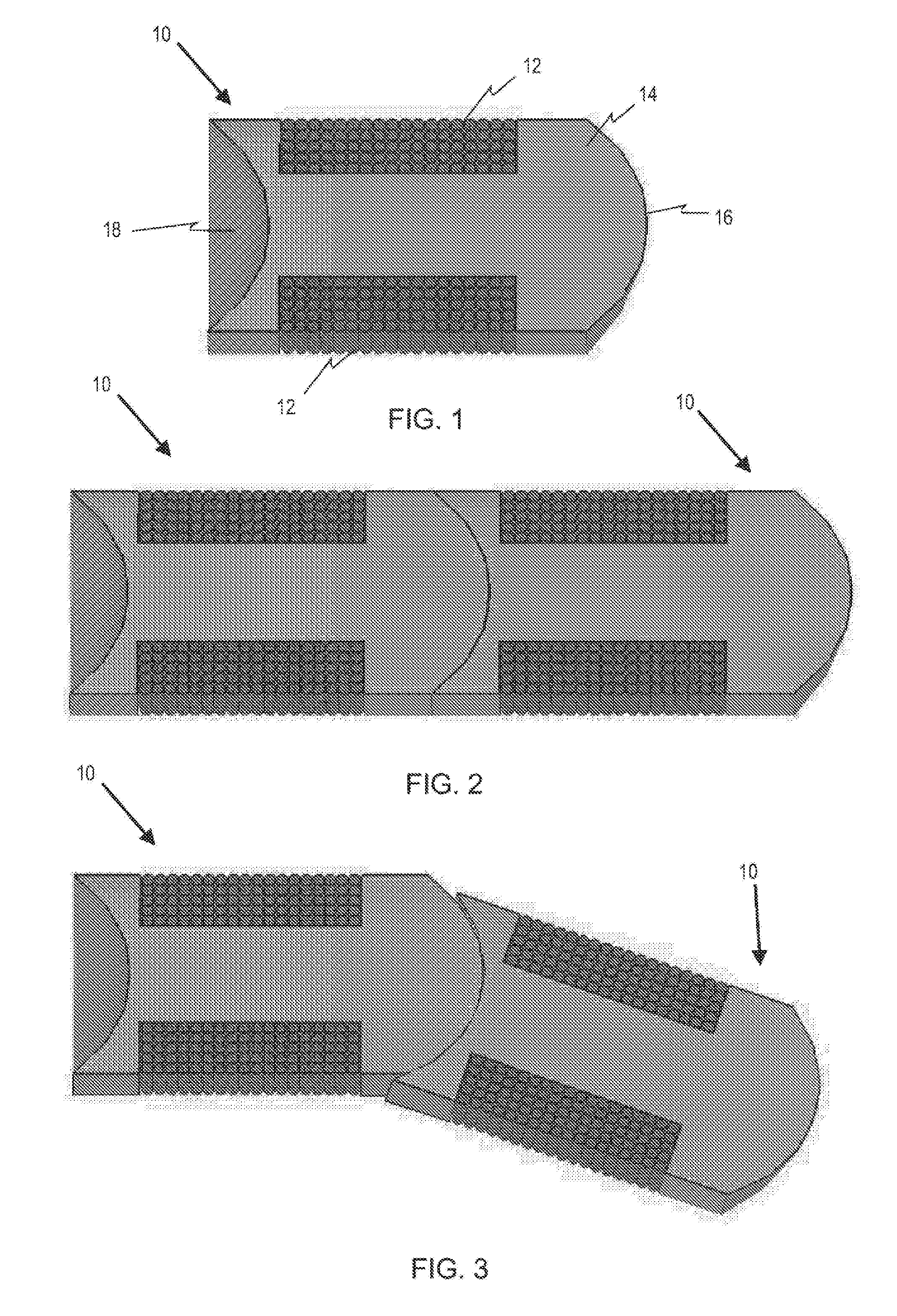
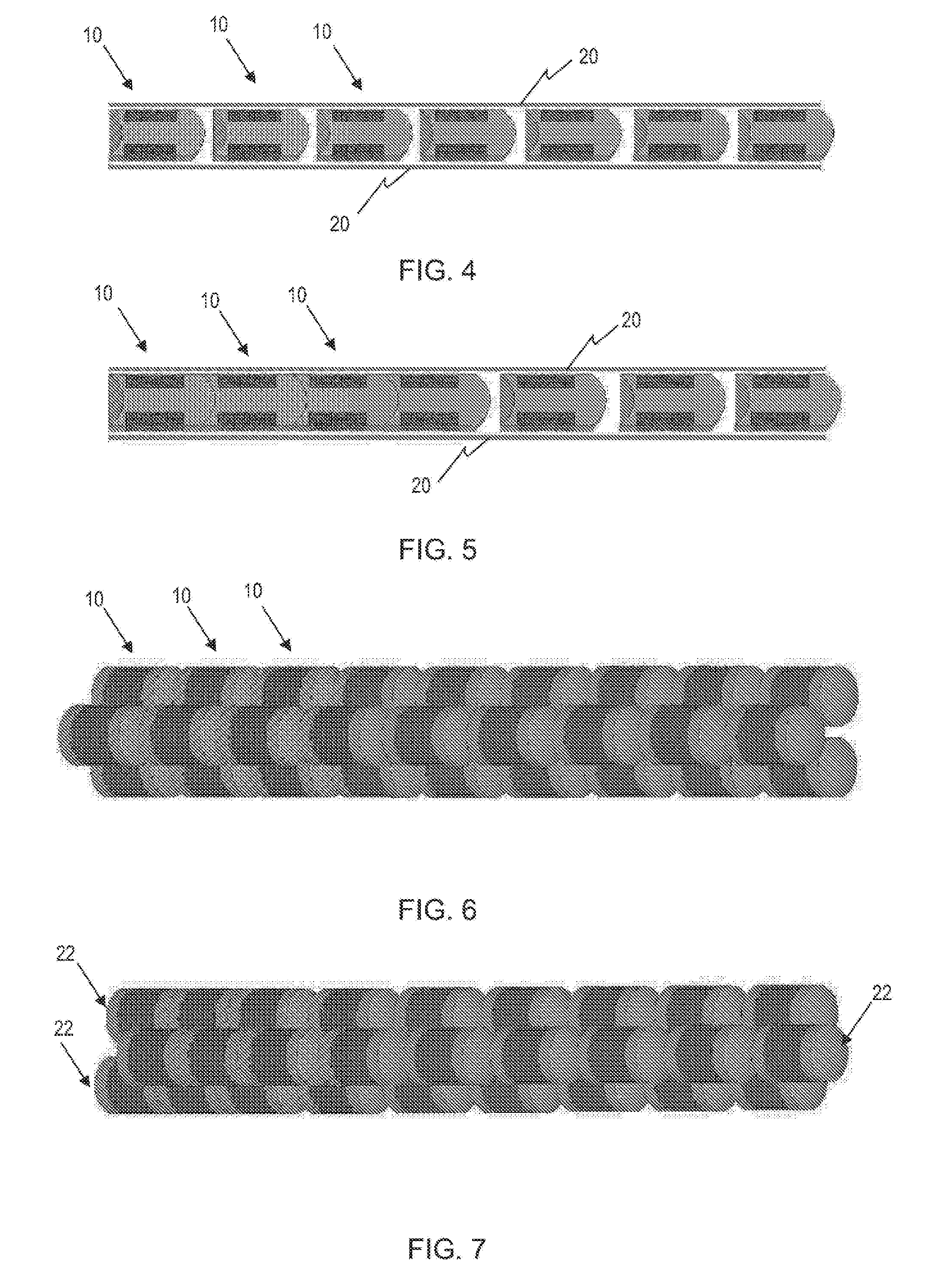
The present invention provides an electromagnetic device comprising: a power circuit, and a contact initiated electro-magnet having an electrical coil in operable connection with the power circuit, wherein one end of the electrical coil is directly connected to the power circuit and the other is connected to the magnetic core of the electromagnet such that, in use, the magnetic core performs the dual purposes of (i) focusing the electromagnetic field created by the coil and (ii) forms part of the electrical circuit that energizes the magnetic core of the electromagnet. Multiple electromagnetic devices may be combined to form a kinetic device capable of creating an electrically-based movement device that mimics the form and function of the skeletal muscle through the use of multiple contact initiated electromagnets held within elastic tubes.

Description

FIELD OF THE INVENTION[0001]The present invention is in the field of bioengineering, and particularly in biomechanical engineering.BACKGROUND TO THE INVENTION[0002]As the global population ages and social structures change, our frail and disabled will need automated assistance to perform normal daily activities independently as support services become less available.[0003]All current approaches to duplicating the skeletal muscle have taken the approach to replace a muscle mass with contrivances such as hydraulic / pneumatic ram-like devices, electric motor with gears / pulleys, pneumatic bladders. As a consequence, in order to achieve the necessary performance, these devices are bulky, require a sizeable power supply and are generally only capable of providing force between two anchor points along a straight line.[0004]Furthermore current approaches typically require complex control systems to first sense and then control the amount of movement required to apply the required force to ac...

Claims


Application Information

Patent Timeline
IPC IPC(8): A61F2/08
CPCA61F2/08A61F2250/0001A61F2002/482A61F2002/0894H01F7/066H01F7/081H01F2007/086A61F2/482
Inventor LIZZIO, ANDREW
Owner CLARUS TECH
Why Eureka
Try Eureka