Eureka AIR delivers breakthrough ideas for toughest innovation challenges, trusted by R&D personnel around the world.

Adjustable support device for the knee

a support device and knee technology, applied in the field of adjustable support straps, can solve the problems of compromising the maximum amount of pressure the strap is actually capable of achieving and unable to adequately relieve the discomfort of the wearer, and inefficiently and incorrectly applying to the knee, so as to prevent the loss of the attachment element

Inactive Publication Date: 2003-10-02
MEDICAL SPECIALTIES
View PDF29 Cites 37 Cited by
  • Summary
  • Abstract
  • Description
  • Claims
  • Application Information

AI Technical Summary

Benefits of technology

[0013] According to yet another preferred embodiment of the invention, the primary tensioning device includes an opening defined by and extending through the strap adjacent the first end. The opening is adapted for receiving the second end of the strap therethrough, thereby permitting the tension on the strap to be increased prior to placing the strap in the primary tension position and without removing the strap from around the knee.
[0055] FIG. 5 shows the manner in which certain of the components of the applicator 45 are positioned within the compartment 60. The applicator 45 is assembled so that each string segment 56A extends through one of four eyelets 62 located on the front panel 14. One end of each string segment 56A is sandwiched between the elastomeric patches 47 and 48 so that two of the segments 56A are attached to each one of two opposing side edges 67 and 68, respectively. Side edges 67 and 68 are then sewn together to form the central patch 51. The other ends of each pair of string elements 56A extend to the outside of the front patch 14 and are connected to side edge 58 of one of the two fastener patches 53. As is shown in FIG. 5, the central patch 51 is positioned within compartment 60 so that it directly overlies the rod 52 and patch 53. This orientation is also shown in FIG. 6, and results in an increased application of force by the central patch 51 on the rod 52 when the pressure applicator 45 is being adjusted relative to the strap 11 (See FIGS. 10 through 12).

Problems solved by technology

While prior art straps and other devices exist which attempt to alleviate pain associated with the knee, knee joint and related tissues, such devices seldom apply a sufficient amount of pressure to the affected area to adequately relieve the discomfort suffered by the wearer.
To the extent such devices do manage to apply any pressure to the knee, such pressure is usually distributed equally across the device and is thus inefficiently and incorrectly applied to the knee.
Furthermore, the manner in which the ends of prior art straps extend around the knee, overlap each other and are connected together compromises the maximum amount of pressure the strap is actually capable of achieving and applying to the knee.
This is because a small amount of the tension achieved in the strap when the strap is stretched around the knee is inevitably lost when the wearer loosens his or her grip on one end of the strap so that the other end can be connected thereto.

Method used


Image

  • Adjustable support device for the knee
  • Adjustable support device for the knee
  • Adjustable support device for the knee

Examples


Embodiment Construction

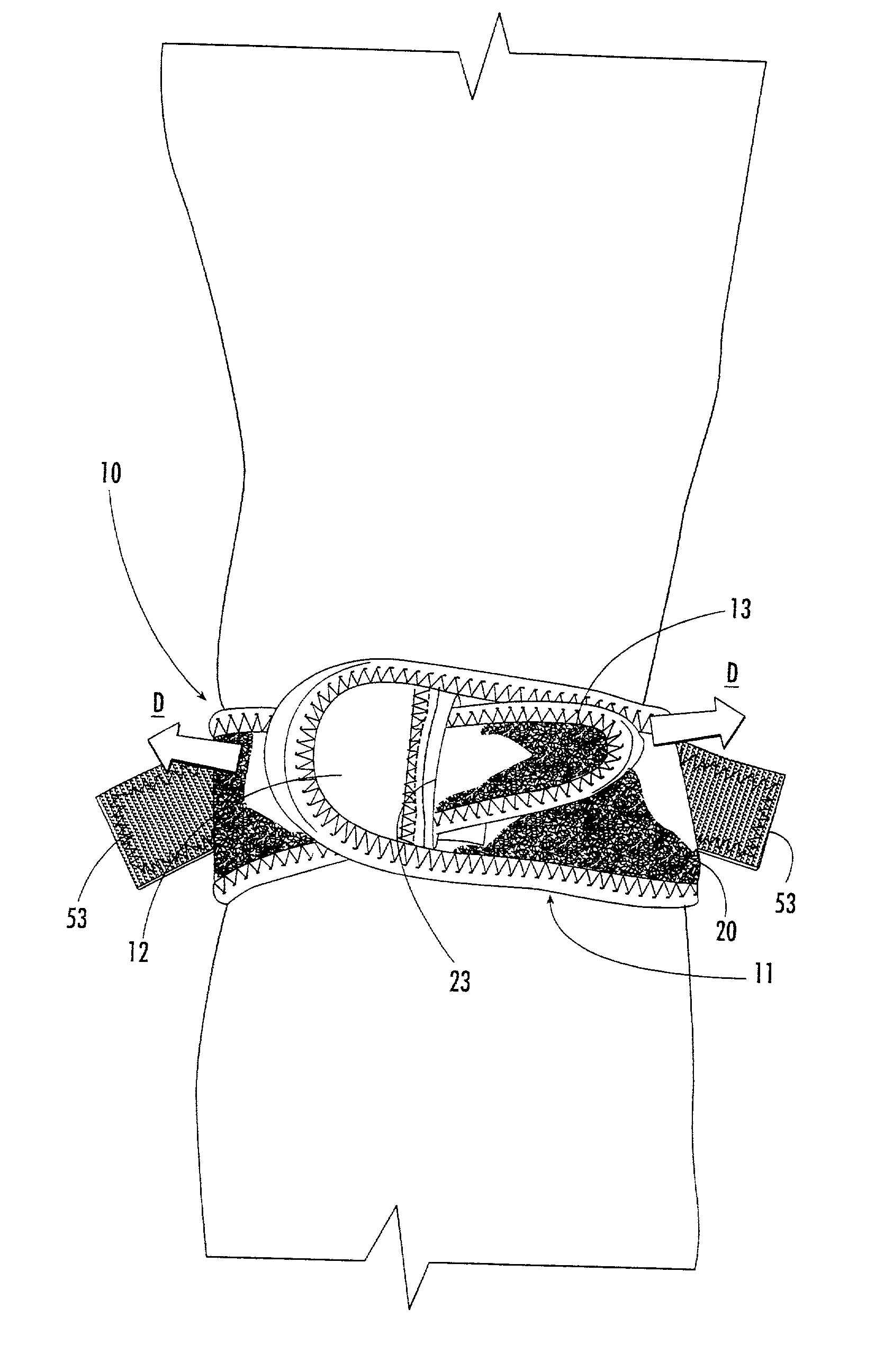
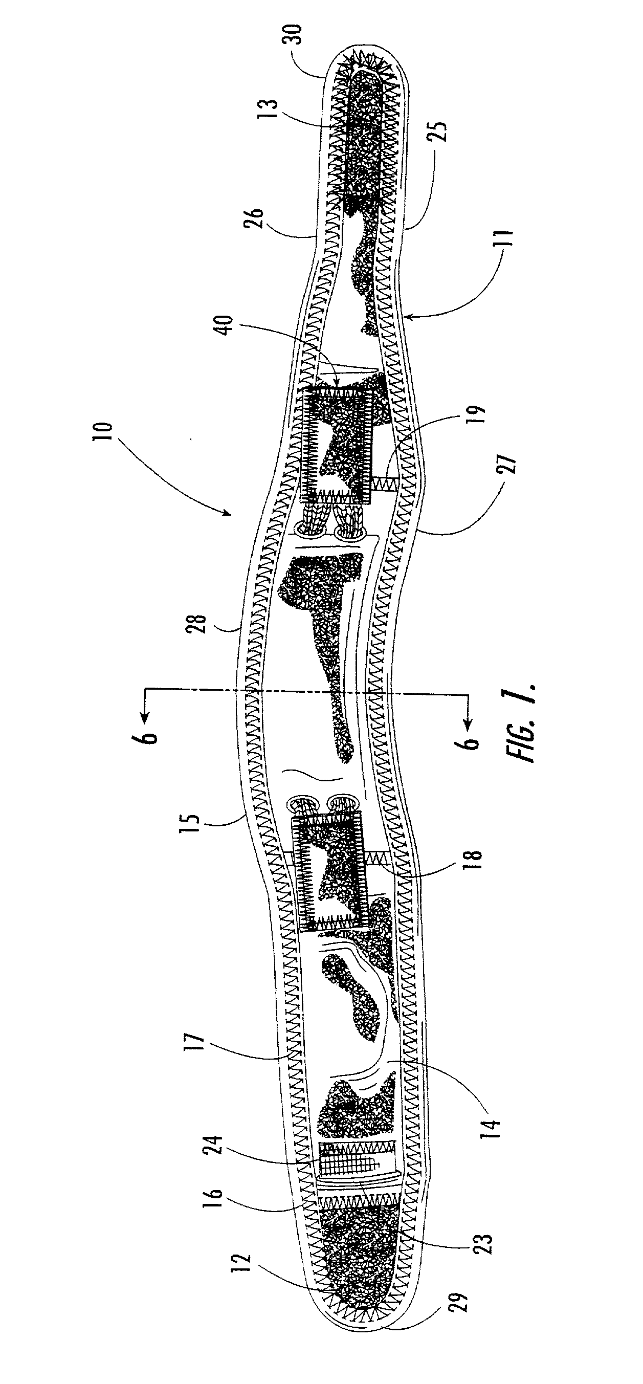
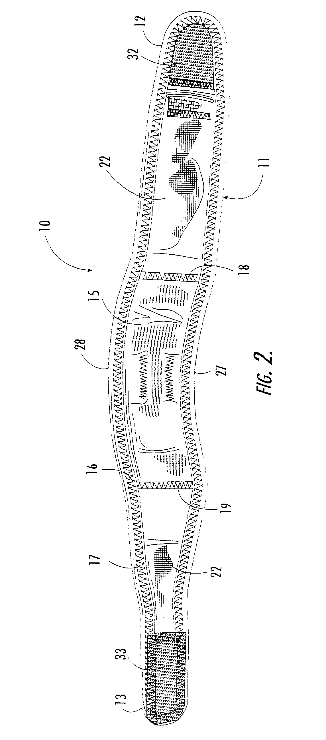
[0046] Referring now generally to the drawings, an adjustable patellar support is illustrated in FIG. 1 and shown generally at reference numeral 10. The support 10 includes an elongate strap 11 that has first and second ends 12 and 13. The strap 11 is formed from a front panel 14 and a back panel 15 (see FIG. 2) which are overlaid with each other. The peripheral edge of panel 14 and one of the pairs of opposing side edges of back panel 15 are joined together and covered by a narrow strip of binding 16, which is preferably attached to the strap 11 using a row of zig-zag stitches 17 that extends around the perimeter of the front panel 14 adjacent the peripheral edge. Additional seams 18 and 19 formed by respective rows of zig-zag stitches extend across the width of the strap 11 and the back panel 15 to the front panel 14.

[0047] Although the front panel 14 may be formed from any suitable material, the front panel 14 is preferably formed from a neoprene replacement material having a rai...


PUM


Abstract

An adjustable support device for the knee, including a strap having at least one elastic portion and first and second ends. A primary tensioning device is positioned on the strap for securing the strap around the knee and positioning the strap in a primary tensioned position relative to the patella, knee joint, and attachment sites of the connective tissues of the knee joint. A secondary tensioning device is also carried by the strap and includes an elastic element and at least one attachment member for being placed in a secondary tensioned position relative to the strap for increasing the tension of the strap and applying concentrated radially-directed support pressure to, the knee joint, attachment sites of the connective tissues of the knee joint, and an anterior aspect of the patella.

Description

TECHNICAL FIELD AND BACKGROUND OF THE INVENTION[0001] This invention relates to an adjustable support strap for use in alleviating pain associated with a variety of conditions affecting the knee. Although the support strap of the present invention is specifically intended for use by athletes to correct deficiencies in patellar tracking and to treat patellar tendonitis, the support strap is equally suited for use in treating individuals who suffer from a variety of conditions affecting the knee and who require supplemental support to relieve pain and / or preserve the mobility of the knee joint. The support strap is thus suitable for alleviating the symptoms of several conditions including, but not limited to, injuries to the anterior and posterior cruciate ligaments, the medial and lateral collateral ligaments, and injuries that cause the various muscular etiologies of patellofemoral pain syndrome.[0002] While prior art straps and other devices exist which attempt to alleviate pain as...

Claims


Application Information

Patent Timeline
IPC IPC(8): A61F5/01A61F5/32
CPCA61F5/32A61F5/0106
Inventor GAYLORD, ERIC LEE
Owner MEDICAL SPECIALTIES
Why Eureka
Eureka Blog
Learn More