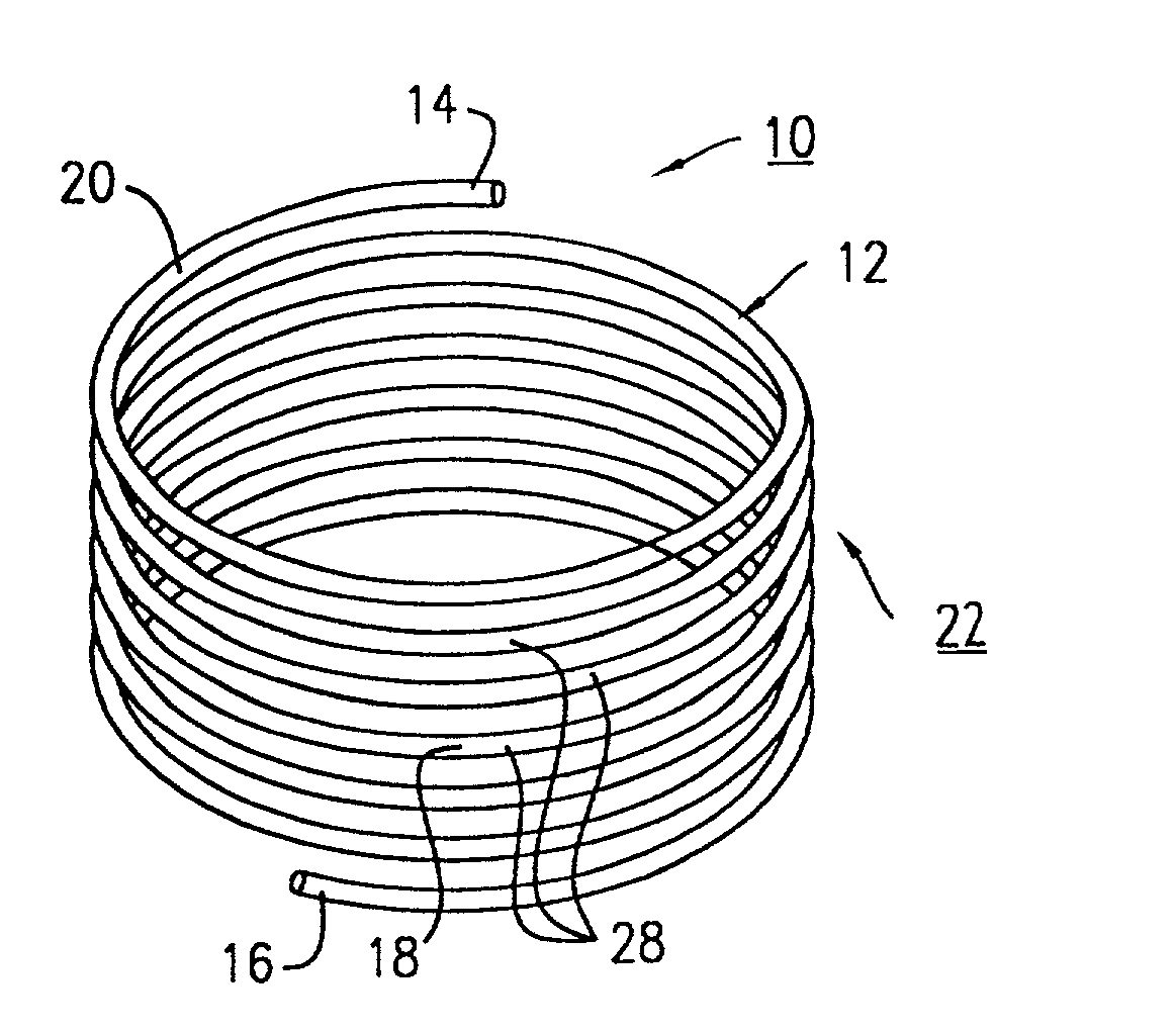
Suture anchoring and tensioning device and method for using same

a technology which is applied in the field of suture anchoring and tensioning device and method for using same, can solve the problems of pressure holding and inability to achieve good sets

Inactive Publication Date: 2003-10-16
ETHICON INC
View PDF42 Cites 101 Cited by
  • Summary
  • Abstract
  • Description
  • Claims
  • Application Information

AI Technical Summary

Benefits of technology

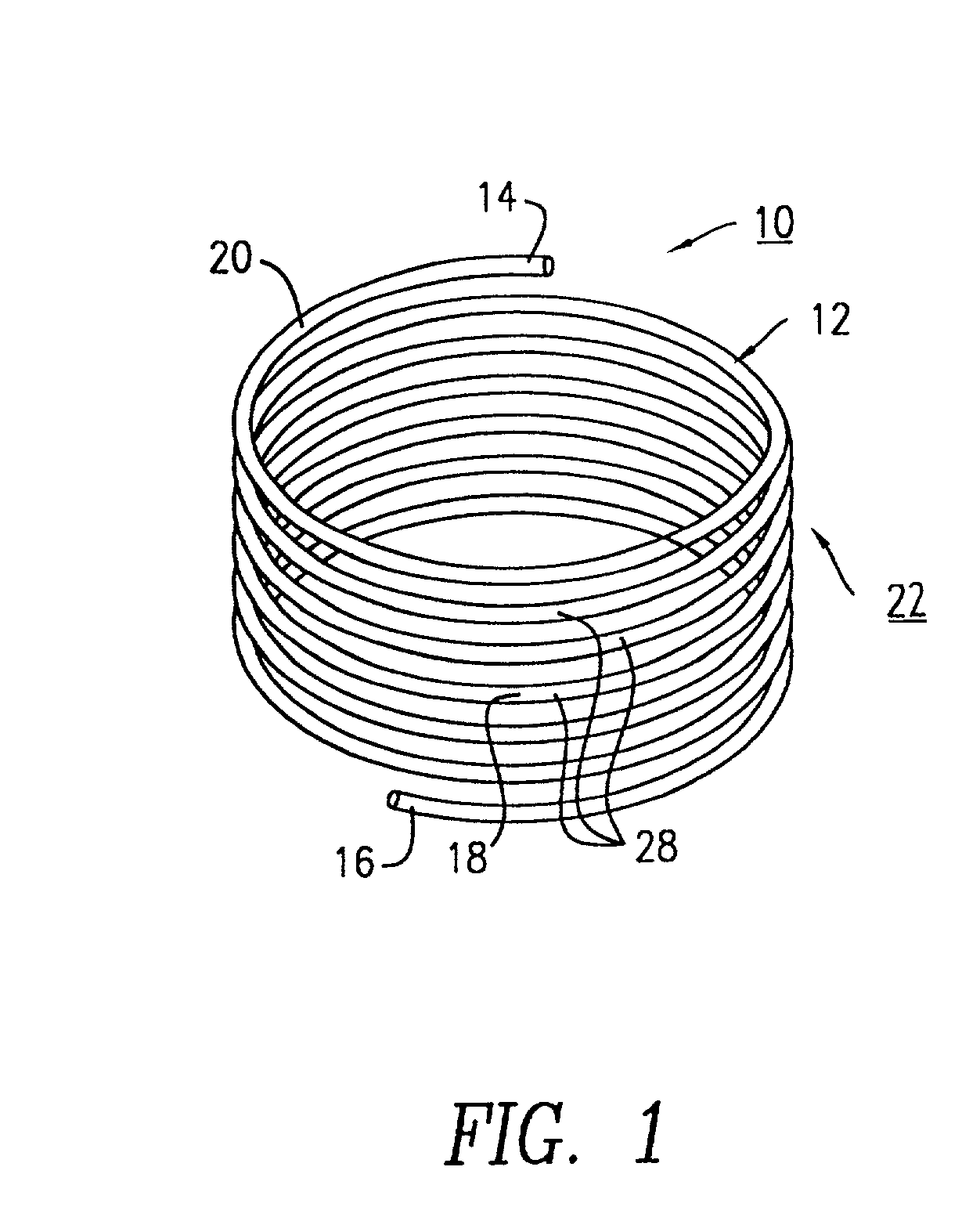
[0011] Another object of the present invention is to provide a helical suture anchoring device that eliminates manual knot tying by the surgeon performing the surgical procedure.
[0013] Another object of the present invention is to provide a helical suture anchoring device that is at least as strong as conventional surgical knots.
[0015] A still further object of the present invention is to provide a helical suture anchoring and tensioning device that is simple to use, and would require only minimal training by the surgeon.

Problems solved by technology

The opening of the clamp is slightly smaller than the diameter of the suture, thereby resulting in a pressure hold when the suture is passed through the suture clip.
There is a possibility of not achieving a good set, as the snap may not have been properly actuated, or it may have been inadvertently released.

Method used


Image

  • Suture anchoring and tensioning device and method for using same
  • Suture anchoring and tensioning device and method for using same
  • Suture anchoring and tensioning device and method for using same

Examples


first embodiment

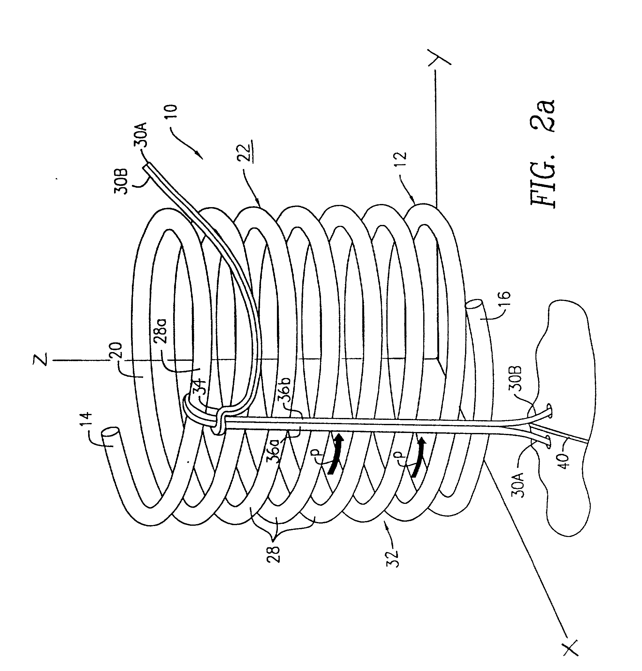
[0042] FIGS. 5a and 5b demonstrate yet another method of attaching a single suture 30 to the helical anchoring device 10 on an incision site 44 at the end stitch point 42b for a running stitch surgical procedure. With reference to FIG. 5a, the single suture 30 is initially looped over multiple helically-coiled turns 28 starting from the second lowest coiled turn 28b and subsequently looped over an upward coiled turn 28a (see FIG. 5a). This looping-over step does not have to go to the uppermost coiled turn 28, as the looping-over step could start on any of the upper coiled turns 28. The suture 30 is rotated in the sense of the downward path P while being moved away (upward) from the incision site 44. The suture 30 is then wound from the aforementioned coiled turns 28 (the upward position) of the uppermost coiled turn 28a through each of the helically-coiled turns 28 via the helical path P (downward) to the lowermost coiled turn 28b of device 10. As shown in FIG. 5b, the single suture...

second embodiment

[0054] In operation, the helical suture anchoring device 310 in combination with the single suture 330 may be used in various surgical procedures. For example, as shown in FIG. 10, the device 310 is used for securing the single suture 330 on an incision site 356 for a given surgical procedure. With reference to FIG. 10, the device 310 is positioned and placed in close proximity to an end stitch point 356b on the incision site 356 for securing the single suture 330 thereto. The single suture 330 is hooked around the L-shaped hook member 352 such that a portion of suture 330 is positioned parallel to the Z-axis along the outer side 332 of the coiled turns 328. The single suture 330 is then wound through each of the coiled turns 328 via the helical path P of device 310. Referring still to FIG. 10, the single suture 330 is wrapped about each of the coiled turns 328 of the coiled member 312 such that the suture 330 is frapped about itself, resulting in the lashing of suture 330 to the de...


PUM


Abstract

A suture anchoring device is made from a coiled member having a helical configuration with a multiplicity of turns. When used in connection with a surgical procedure, the device is positioned adjacent to a wound site and a suture is attached to at least two of the turns so as to anchor the suture to the coiled member.

Description

[0001] The present invention relates to a suture anchoring and tensioning device for use with sutures in surgical procedures.[0002] In surgical procedures sutures are commonly used to close incisions and to reunite damaged tissue. Typically, the sutures are maneuvered and passed through the affected tissue and the free ends of the sutures are individually tied together by the surgeon. In most surgical incisions, the surgical site area is sufficiently exposed to permit the surgeon to access and quickly tie the suture manually with a surgical knot. However, in other surgical procedures, such as endoscopic procedures, laparoscopic procedures, arthroscopic procedures and the like, or when robotic surgical procedures occur, the suturing site is inaccessible to the surgeon's hands. As a result, the surgeon must tie each of the suture ends into a knot at location remote from the suturing site, and then manipulate suitably configured instruments for sliding the surgical knot to the suturing...

Claims


Application Information

Patent Timeline
Patent Type & Authority Applications(United States)
IPC IPC(8): A61B17/00A61B17/04
CPCA61B17/0401A61B17/0487A61B2017/00867A61B2017/0496A61B2017/0454A61B2017/0458A61B2017/0464A61B2017/0443
Inventor COLLIER, JOHNCHATLYNNE, ETAN S.NERING, ROBERTNOZAD, IRENE
Owner ETHICON INC
Why Eureka
Try Eureka