Method for controlling a hydraulic activation unit

a technology of hydraulic activation unit and actuator, which is applied in the direction of fluid clutch, fluid-pressure actuator, fluid coupling, etc., can solve the problems of not being able to control all the movement phases of the controller, unable to use all the controlled movement phases, and relatively uncontrollable movements of the components connected to the hydraulic cylinder

Inactive Publication Date: 2003-10-23
KOMATSU MINING GERMANY
View PDF2 Cites 8 Cited by
  • Summary
  • Abstract
  • Description
  • Claims
  • Application Information

AI Technical Summary

Problems solved by technology

However, such a controller is also subject to uncertainties for the operation of the hydraulic cylinder and cannot be used for all ...

Method used


Image

  • Method for controlling a hydraulic activation unit
  • Method for controlling a hydraulic activation unit
  • Method for controlling a hydraulic activation unit

Examples


Embodiment Construction

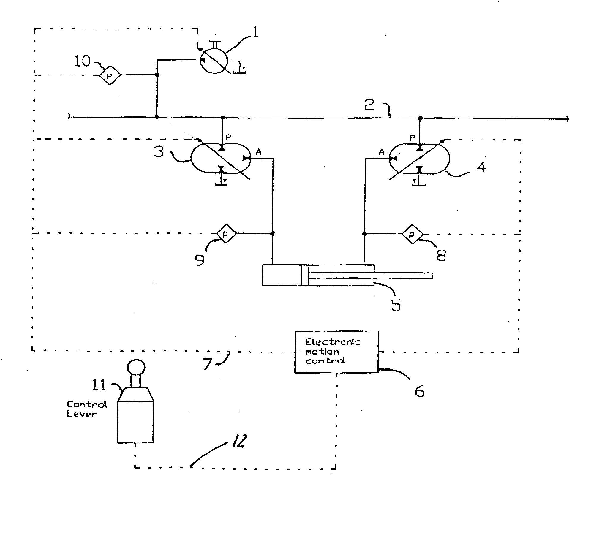
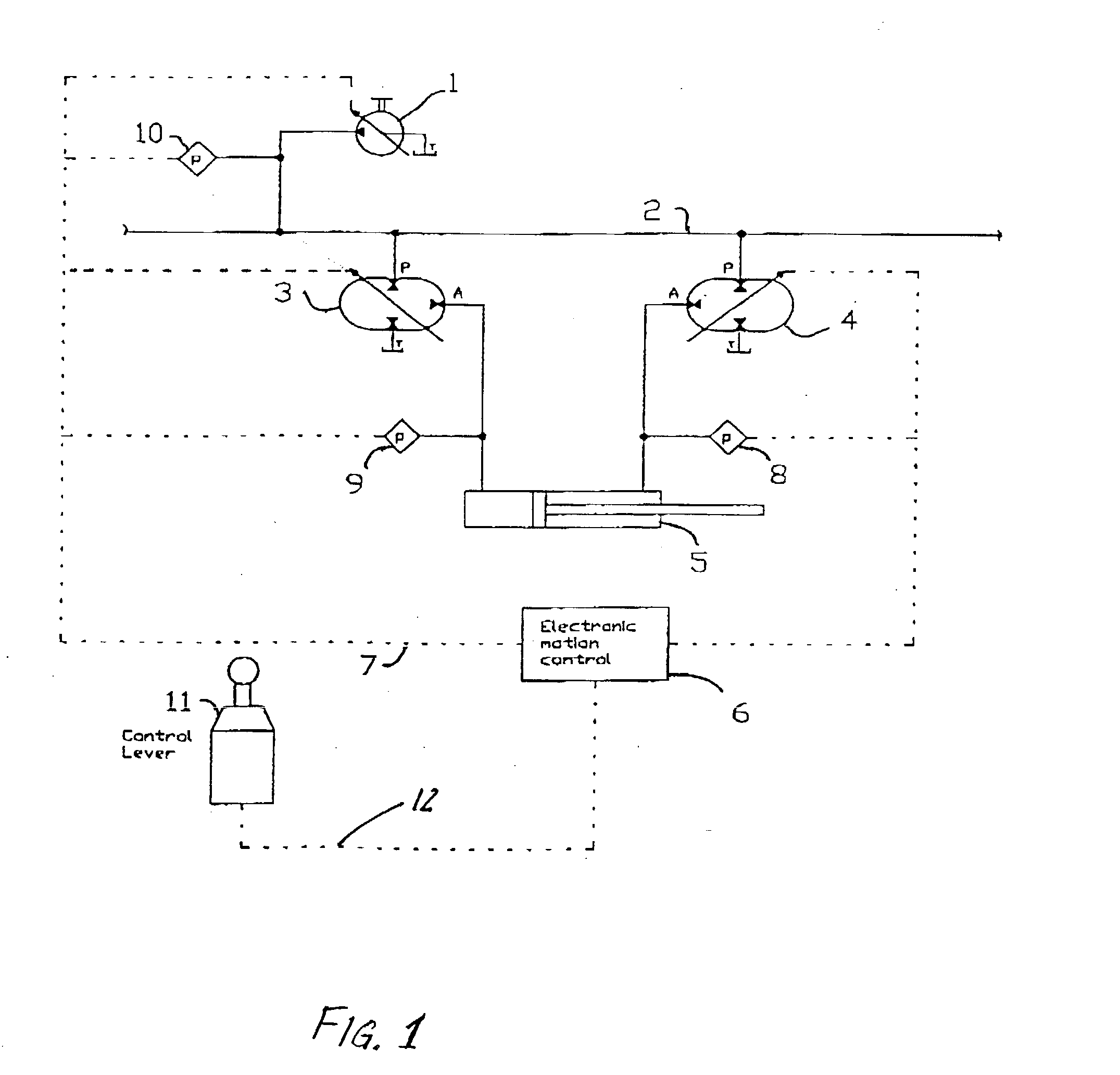
[0014] In FIG. 1, pump 1 generates a volume flow from a reserve tank at a pressure in a common pressure line 2. Hydraulic transformers 3, 4 are connected to pressure links.

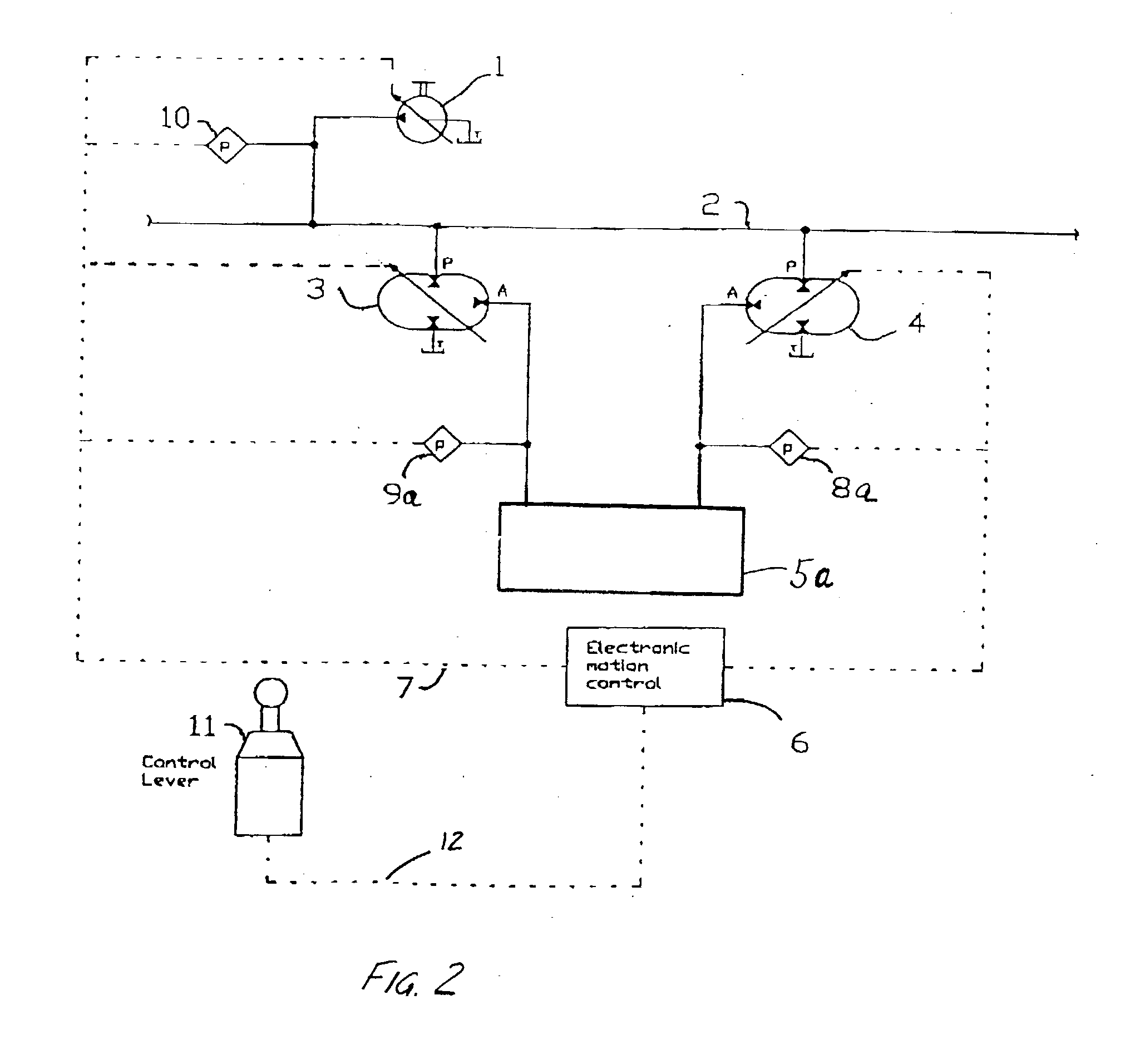
[0015] Pressure measuring devices 8, 9, 10 are connected to the pressure lines between hydraulic transformers 3, 4 and a hydraulic power unit for consuming hydraulic pressure as generating a force. In an embodiment shown in FIG. 1, the hydraulic power unit is a hydraulic cylinder 5. In an embodiment shown in FIG. 2, the hydraulic power unit is a hydraulic motor 5a.

[0016] With reference to FIG. 1, the controller 6, referred to in the drawing as "electronic motion control" is connected via the line 7 to the pump 1, the hydraulic transformers 3, 4, the pressure measuring devices 8, 9, 10. Controller 6 is also connected to control lever 11 and to other measuring devices (not shown).

[0017] Flow control, i.e. direction and rate, is interpreted as an actuation signal by the control electronics 6 by means of the pressures...


PUM


Abstract

A method of controlling an hydraulic activation unit includes the steps of using a characteristic diagram of a first hydraulic transformer as an input variable in the control unit; using a characteristic diagram of a second hydraulic transformer as an input variable in the control unit; and activating the hydraulic actuator responsive to the input variables. The hydraulic activation unit includes the hydraulic power unit, such as a hydraulic actuator or a hydraulic motor, for producing a force. The first hydraulic transformer is operably connected to a first side of the actuator for supplying a pressure. The second hydraulic transformer is operably connected to a second side of the actuator for supplying a pressure. The control unit for assessing the first and second hydraulic transformer operably activates the hydraulic actuator.

Description

1. PRIORITY CLAIM[0001] This application claims priority to application DE 102 14 225.4 filed on Mar. 22, 2002 in Germany.2. FIELD OF THE INVENTION[0002] The invention relates to a method for controlling a hydraulic activation unit. In particular the invention relates to controlling the use of two hydraulic transformers per hydraulic cylinder, as used in construction machinery.3. BACKGROUND OF THE INVENTION[0003] A controller for hydraulic transformers was proposed at the "Sixth Scandinavian International Conference of Fluid Power" (1999, Tampere, Finland) by P. Achten and Dr. J. O. Palmberg. Instead of the customary controller with control valves, a hydraulic transformer was proposed.[0004] Furthermore, S. Rotthuser and P. Achten have disclosed in the periodical "O+P" No. 42, (1998) a circuit with a hydraulic transformer at each of the two terminals of a hydraulic cylinder. However, no further details were given on the necessary controller or regulator.[0005] The controller propose...

Claims


Application Information

Patent Timeline
IPC IPC(8): F15B11/02F15B11/08F15B21/14
CPCF15B11/02F15B11/08F15B21/14F15B2211/20553F15B2211/20569F15B2211/7053F15B2211/6309F15B2211/6313F15B2211/6346F15B2211/6652F15B2211/214
Inventor BAER, MARTINGRANER, KLAUS
Owner KOMATSU MINING GERMANY
Why Eureka
Try Eureka