
Utility device having an improved rotatable drive mechanism

Inactive Publication Date: 2003-10-30
UNVERFERTH MFG
View PDF4 Cites 11 Cited by
  • Summary
  • Abstract
  • Description
  • Claims
  • Application Information

AI Technical Summary

Benefits of technology

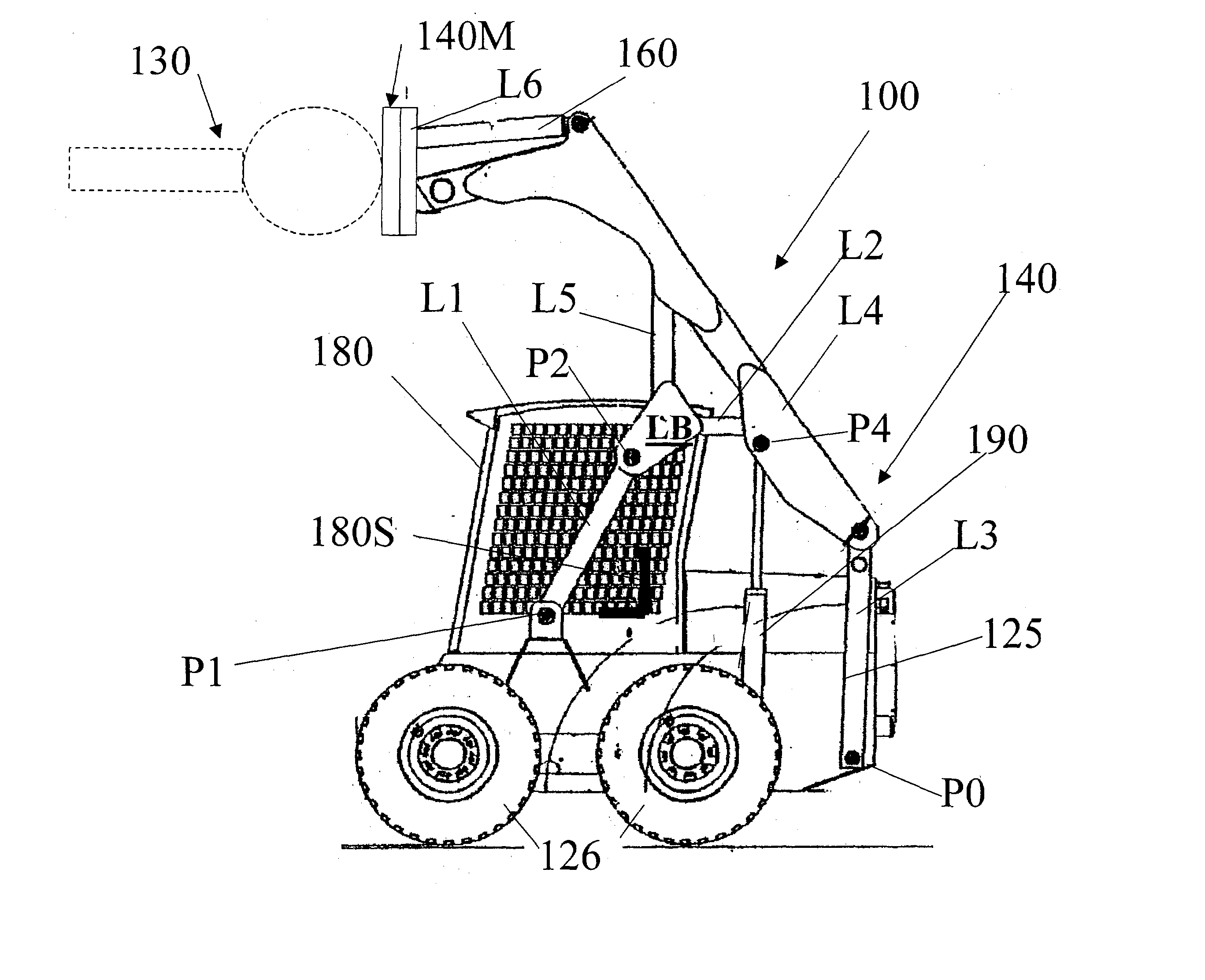
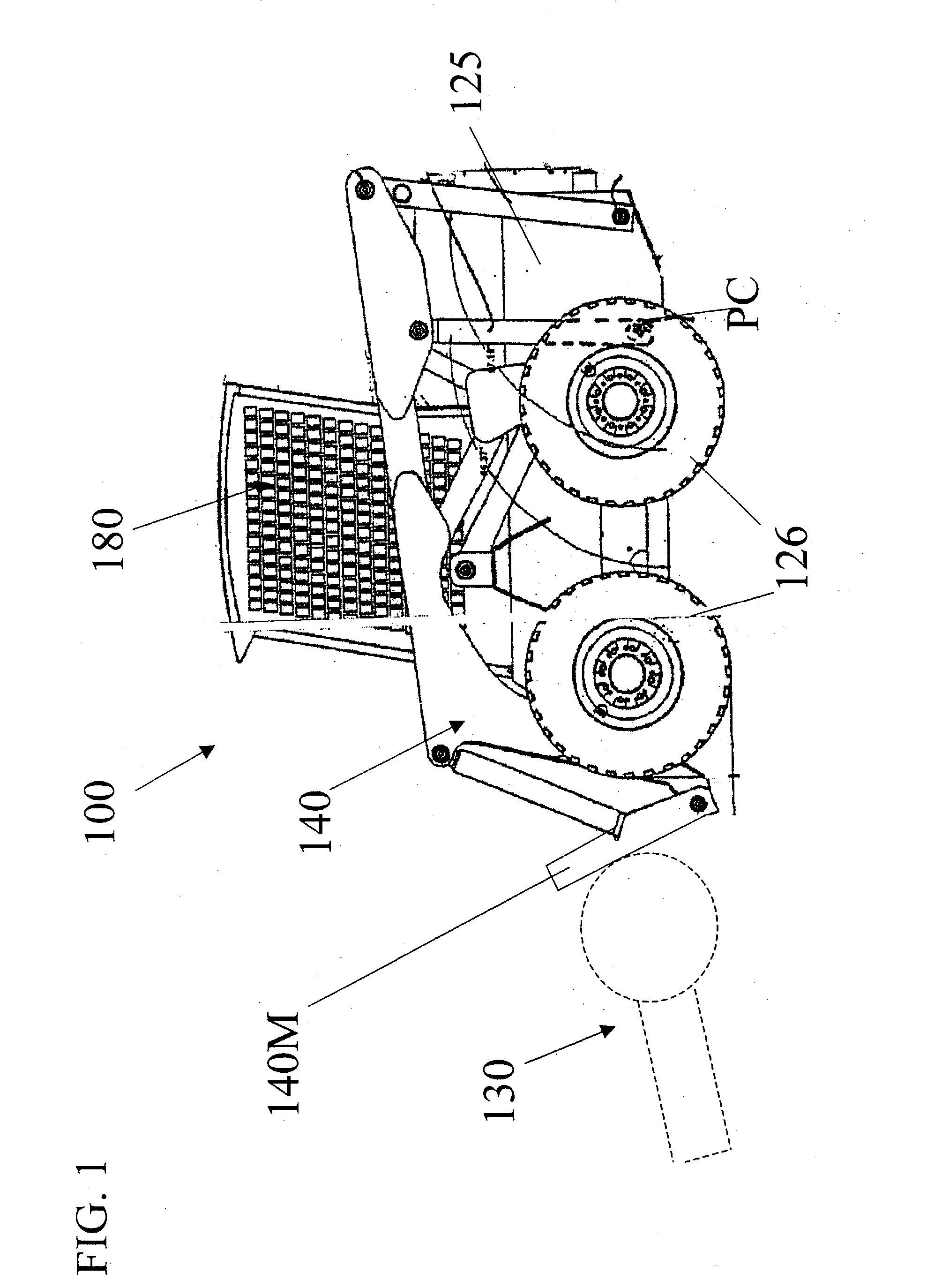
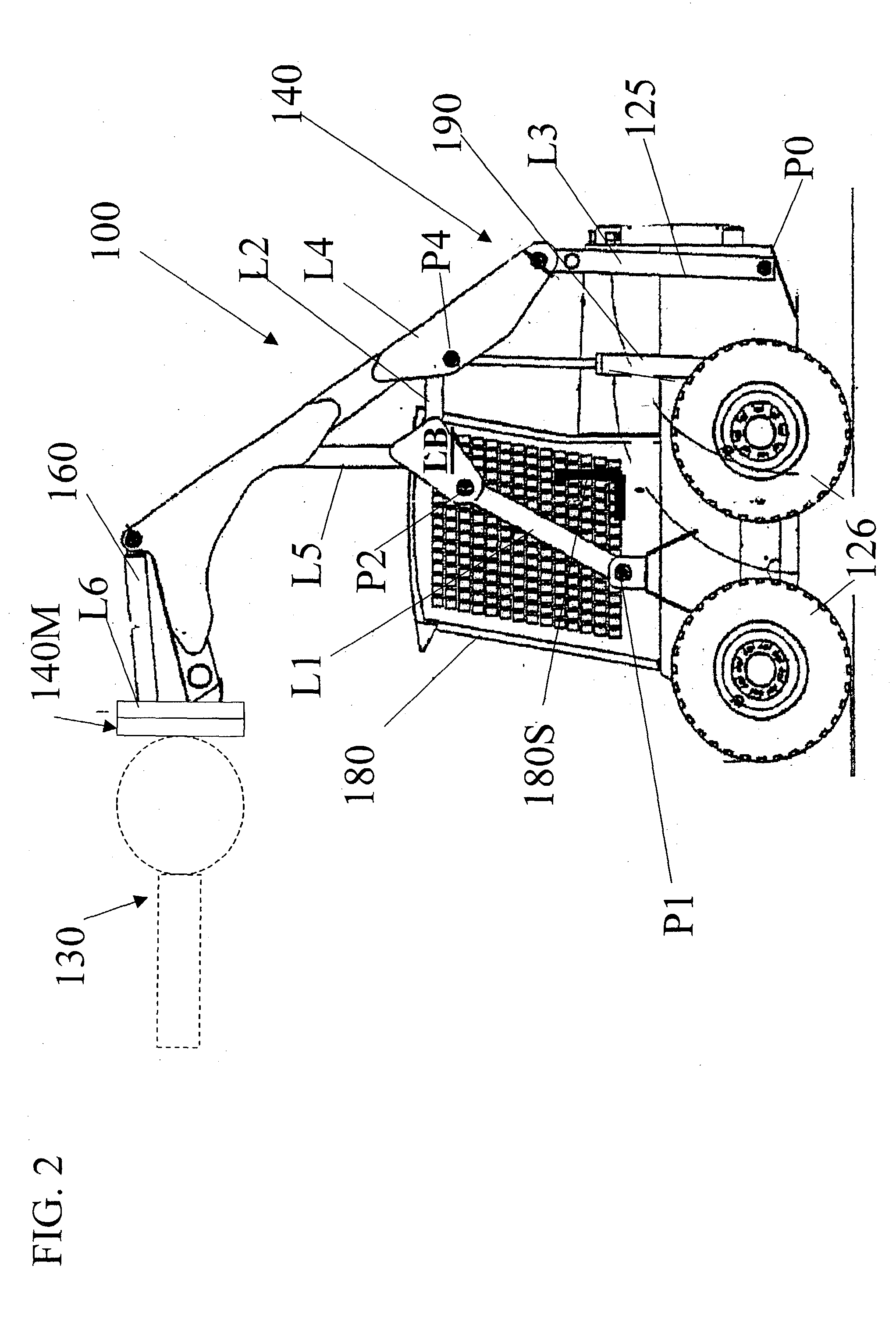
[0009] The preferred embodiments of the present invention can significantly improve upon existing systems and methods. In some preferred embodiments, a utility vehicle is provided that has an improved rotated drive mechanism.

Problems solved by technology

Nevertheless, existing devices have a variety of limitations.

Method used


Image

  • Utility device having an improved rotatable drive mechanism
  • Utility device having an improved rotatable drive mechanism
  • Utility device having an improved rotatable drive mechanism

Examples


Embodiment Construction

[0009] The preferred embodiments of the present invention can significantly improve upon existing systems and methods. In some preferred embodiments, a utility vehicle is provided that has an improved rotated drive mechanism.

[0010] In some embodiments, a utility vehicle or other device for excavating soil or the like includes a utility mechanism, such as, e.g., a trencher, an auger or the like, with a motor-driven utility drum. In preferred embodiments, the motor is contained substantially entirely inside the drum. Preferably, the drive shaft is operatively connected to the drum to rotate the drum at a connection location that is displaced inward from ends of the drum. In some embodiments, the drive shaft is also preferably operatively connected to a second utility mechanism, such as, e.g., a trencher chain. In some embodiments, a planetary transmission is also located inside the drum.

[0011] In some embodiments, a soil-engaging utility device having a utility mechanism with a motor-...


PUM


Abstract

A utility vehicle or other device for excavating soil or the like includes a utility mechanism, such as, e.g., a trencher, an auger or the like, with a motor-driven utility drum. In preferred embodiments, the motor is contained substantially entirely inside the drum. Preferably, the drive shaft is operatively connected to said drum to rotate the drum at a connection location that is displaced inward from ends of said drum. In some embodiments, the drive shaft is also preferably operatively connected to a second utility mechanism, such as, e.g., a trencher chain. In some embodiments, a planetary transmission is also located inside said drum.

Description

[0001] The present application claims priority to Provisional Patent Application Serial No. 60 / 364,058, filed on Mar. 15, 2002, the entire disclosure of which is incorporated herein by reference.[0002] 1. Field of the Invention[0003] The present invention relates generally to, among other things, utility devices, such as, for example, utility vehicles, having utility mechanisms, such as, for example, trenchers and / or the like with rotated drive mechanisms.[0004] 2. Discussion of the Background[0005] There are a variety of known utility vehicles having utility mechanisms with rotated drive mechanisms. In many instances, utility vehicles are often used for construction and / or other utilitarian purposes, such as, e.g., for lifting, pushing, scraping, digging, plowing and / or various other purposes. In many instances, the vehicles include a) a main body having at least one seat for a vehicle operator (such as, for example, a seat located within a protective cab), b) wheels and / or other s...

Claims


Application Information

Patent Timeline
IPC IPC(8): A01B33/02A01B33/08B62D49/02E02F3/20E02F3/34E02F5/10E02F9/20
CPCA01B33/02A01B33/082B62D49/02E02F5/08E02F3/3414E02F5/06E02F3/20
Inventor SMITH, DAVID R.RECKER, MARK A.
Owner UNVERFERTH MFG
Learn More