Toroidal type continuoulsy variable transmission

Inactive Publication Date: 2006-04-18
TOYOTA JIDOSHA KK
View PDF29 Cites 183 Cited by
  • Summary
  • Abstract
  • Description
  • Claims
  • Application Information

AI Technical Summary

Benefits of technology

[0016]With this construction, the amount of the oil to be fed from the oiling hole is increased, when the temperature of the rolling face of the rotary member, or the temperature of rolling member excesses the criterion value which is set based on the tempering temperature of the rotary member. Therefore, the ro

Problems solved by technology

Therefore, the oiling hole cannot be a factor of concavity and convexi

Method used


Image

  • Toroidal type continuoulsy variable transmission
  • Toroidal type continuoulsy variable transmission
  • Toroidal type continuoulsy variable transmission

Examples


Embodiment Construction

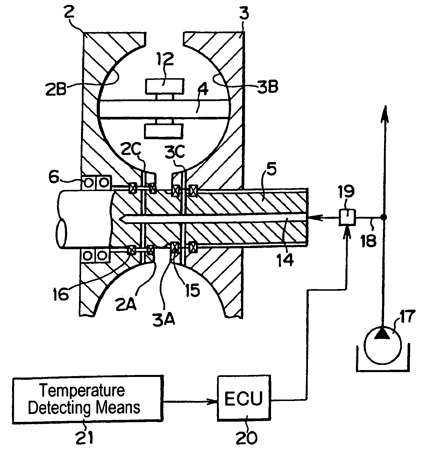
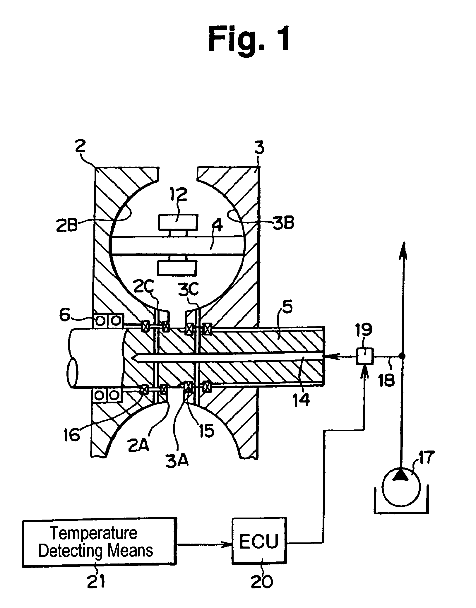
[0021]Next, the present invention will be described in connection with a specific embodiment with reference to the drawings. First of all, to describe one example of a continuously variable transmission subjected to the present invention, double cavity type full toroidal type continuously variable transmission 1 is depicted typically in FIG. 4. According to the toroidal type continuously variable transmission 1, a pair of input discs 2 is arranged in so-called back-to-back relation each other, and a pair of output discs 3 is arranged to be opposed to those input discs 2, namely, with sandwiching those input discs 2.

[0022]Those discs 2 and 3 are made such that portions of their opposed faces on an outer circumferential side from a predetermined radius are shaped, as cut in a plane on the center axis, to have a section of an arcuate plane of a predetermined radius, likewise the disc of the toroidal type continuously variable transmission according to the prior art. And a power roller ...


PUM


Abstract

A toroidai type continuously variable transmission wherein a rolling member is clamped between rotary members; and wherein a rolling face of rotary members being opposed to each other has a curved face, in which its sectional face along the plane including a center axis of rotation is shaped into an arc, in order to allow said rolling face of said rolling member inclining against the center axis of the rotation of said rotary member, characterized by: an oiling hole formed on the portion on the center side of the rotation in said rolling face of the rotary members being opposed to each other, or on the portion on the center side of the rotation leading to said rolling face; and the oil passage for feeding the lubricating oil to the oiling hole, formed on the center side of the rotation in said rotary member, with being communicated with the oiling hole.

Description

TECHNICAL FIELD[0001]This invention relates to a toroidal type (or traction type) continuously variable transmission which is constructed to vary the gear ratio continuously, with clamping a rolling member between a pair of rotary members to transmit a torque to one of the rotary members through the rolling member by rotating the other rotary member, and by varying the torque transmitting point between the rolling member and the rotary member in the radial direction.BACKGROUND ART[0002]A continuously variable transmission of this kind is constructed with, e.g., clamping a disc-shaped roller between a pair of discs arranged opposed to each other. The portions of the pair of discs where is the outer side from a predetermined radius has an arcuate plane congruent with the arc centered on the center point of those opposed planes of those discs, and such arcuate plane is leading to circumferential direction. The plane thus incurved three-dimensionally is a toroidal plane. The toroidal pl...

Claims


Application Information

Patent Timeline
IPC IPC(8): H02P15/00F16H15/38F16H57/04
CPCF16H15/38F16H57/043F16H57/049
Inventor TAKETSUNA, YASUJITAMAKI, SHIGENORI
Owner TOYOTA JIDOSHA KK
Why Eureka
Try Eureka