Starter control device and starter

a technology of starter control and control device, which is applied in the direction of electric control, engine starter, machine/engine, etc., can solve the problems of degrading vibration proof performan

Active Publication Date: 2003-11-20
MITSUBISHI ELECTRIC CORP
View PDF11 Cites 23 Cited by
  • Summary
  • Abstract
  • Description
  • Claims
  • Application Information

AI Technical Summary

Problems solved by technology

Also, a vibration proof performance is degraded.

Method used


Image

  • Starter control device and starter
  • Starter control device and starter
  • Starter control device and starter

Examples


first embodiment

[0017] First Embodiment

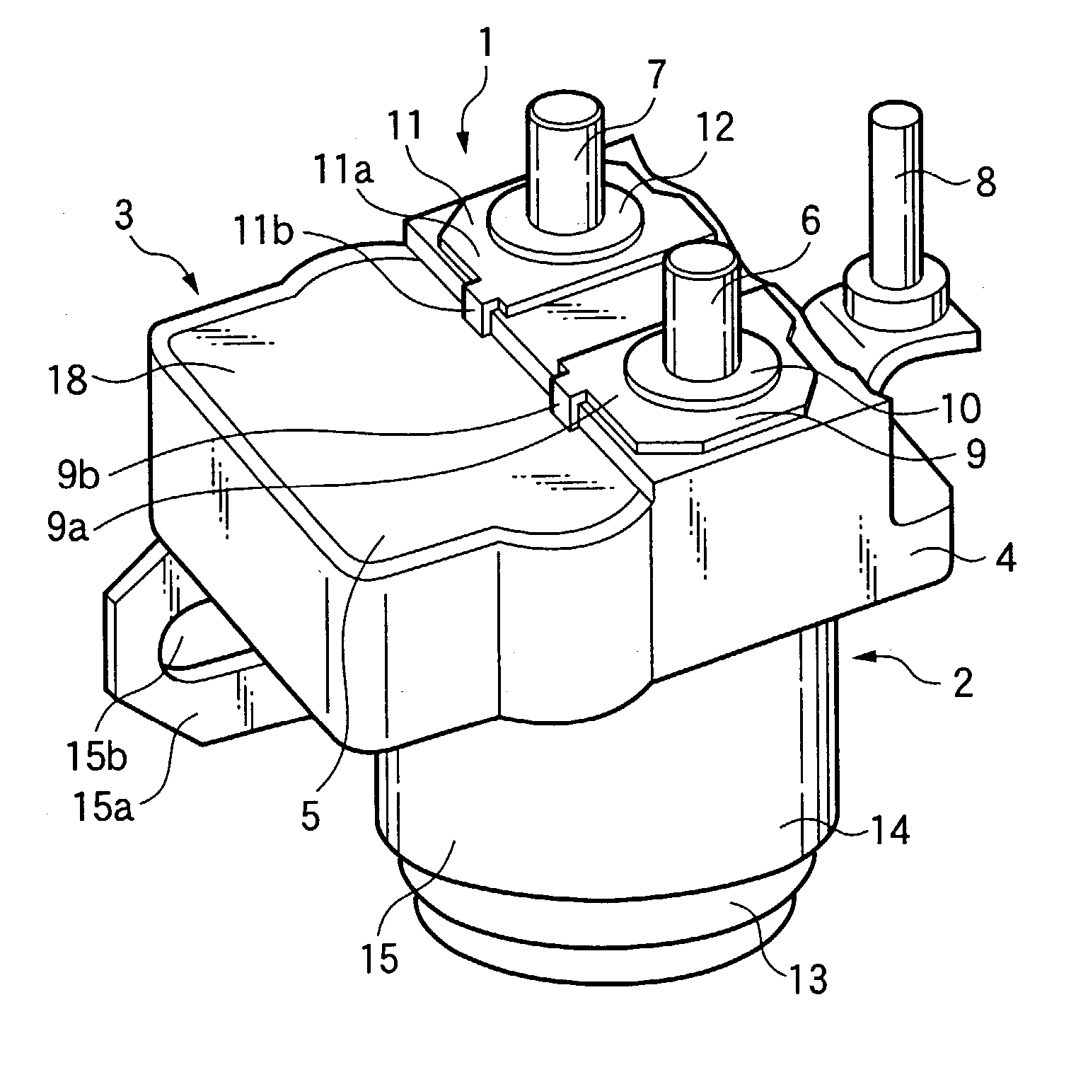
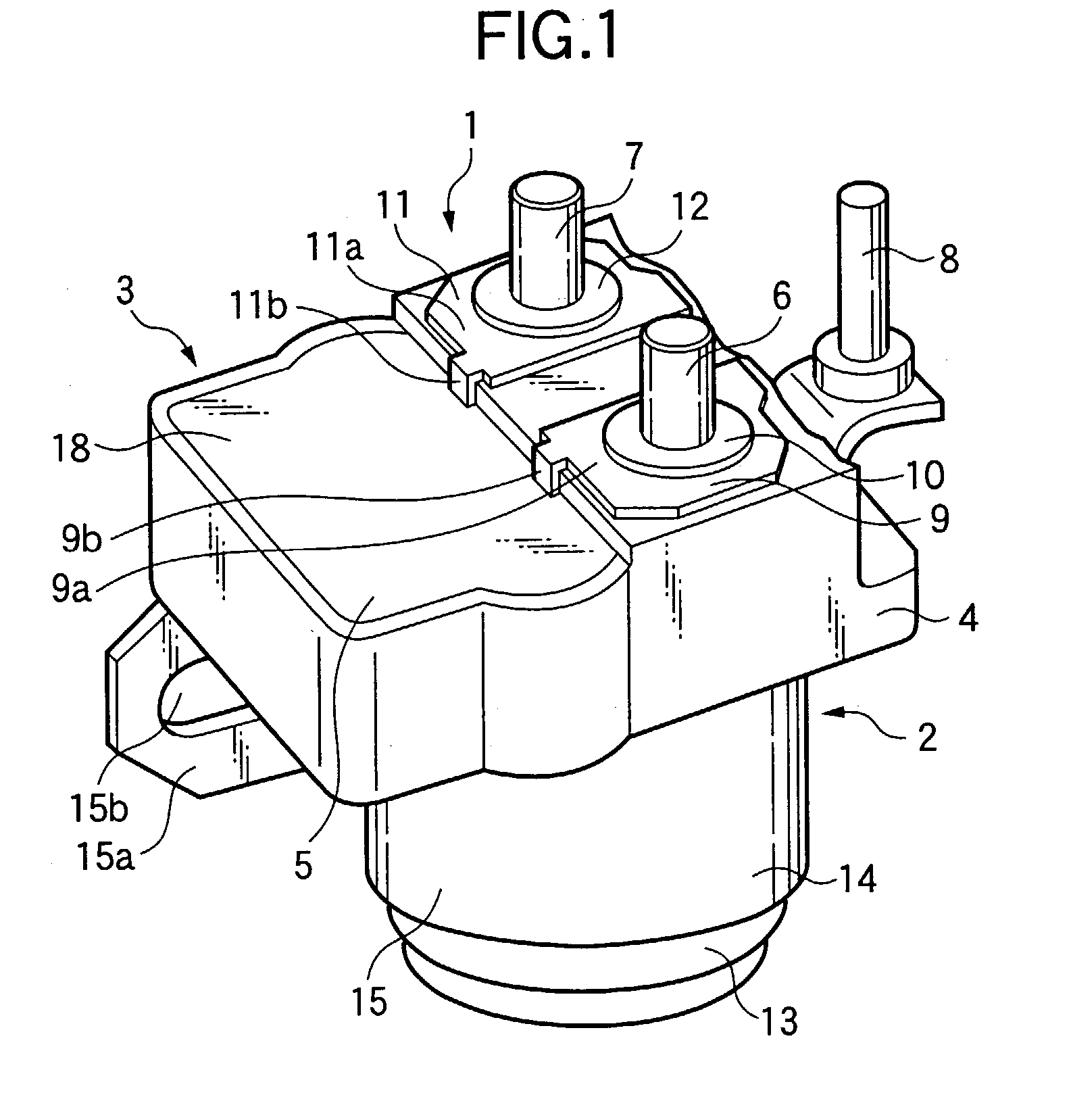
[0018] A first embodiment of the present invention will be described with reference to the accompanying drawings. FIG. 1 is a perspective view showing a starter control device which is a first embodiment of the present invention. FIG. 2 is a cross sectional view showing a main portion of the starter control device of the first embodiment. FIG. 3 is an electric wiring diagram in the first embodiment. FIG. 4 is a circuit diagram showing a control circuit part in the first embodiment. FIGS. 5(a) to 5(f) are timing charts showing an operation of the first embodiment. Throughout those figures, like or equivalent portions are designated by like reference numerals, for simplicity. In FIG. 1, reference numeral 1 is a starter control device, which is integrally formed with an auxiliary switch 2 and a control circuit part 3. A cap 4, made of an insulating material such as a phenolic resin is integrally formed with a housing 5 that contains the control circuit part 3. A ...

second embodiment

[0036] Second Embodiment

[0037] A second embodiment of the invention will be described. FIG. 6 is a perspective view showing a starter control device which is a second embodiment of the invention. A structure of the starter control device of the embodiment is substantially the same as of the first embodiment. In the figure, like reference numerals are used for designating like or equivalent portions in FIG. 1. FIG. 7(a) is a front view showing a control-device contained starter in which the starter control device is incorporated into the starter. FIG. 7(b) is a side view of the starter when seen in a direction of X. In the figure, a control-device contained starter 19a is generally made up of a mechanism part 35, motor unit 22, main switch 23 and starter control device 1. A bracket 36 forming an outer shell of the mechanism part 35 is formed with a conductive member such as an aluminum die casting member. The motor unit 22, main switch 23 and starter control device 1 are integrally m...


PUM


Abstract

A starter control device includes an auxiliary switch for controlling an operation of a starter main switch, the auxiliary switch having a cap made from an insulating member. The starter control device also includes a control circuit part disposed on the cap, a terminal disposed on the cap, and a connection metal attachment for connecting the control circuit part and the terminal.

Description

[0001] 1. Field of the Invention[0002] The present invention relates to a starter control device for controlling a starter to start an engine and a starter having the control device, particularly to a structure in which a control circuit part is provided on a cap of an auxiliary switch.[0003] 2. Description of the Related Art[0004] A conventional device of this type is disclosed in Japanese Patent Laid-Open No. 2000-87831, for example. In a starter protector device thus disclosed, a protector circuit is disposed in a space defined by legs of a mounting bracket of an auxiliary switch. The protector circuit and a terminal provided on a cap of the auxiliary switch are connected to each other by a lead wire.[0005] In the starter protector device thus structured, since the protector circuit and the terminal provided on the cap of the auxiliary switch are connected to each other by the lead wire, a work to remove the insulating cover from the lead wire and a work to apply preliminary sold...

Claims


Application Information

Patent Timeline
Patent Type & Authority Applications(United States)
IPC IPC(8): F02N11/00F02D45/00F02N11/08F02N15/06H01H51/06
CPCF02D2400/18H01H51/065F02N15/067F02N11/087F02N11/08
Inventor HISAMOTO, MOTOIKANZAKI, SYOZO
Owner MITSUBISHI ELECTRIC CORP
Why Eureka
Try Eureka