
Method of and apparatus for pitch period estimation

a technology of pitch period and apparatus, applied in the field of pitch period estimation, can solve the problems of typical annoying crackling noise, data transmission likely to be impaired by interference, and packet loss rate rendering speech quality unacceptable,

Inactive Publication Date: 2003-11-27
TELEFON AB LM ERICSSON (PUBL)
View PDF8 Cites 39 Cited by
  • Summary
  • Abstract
  • Description
  • Claims
  • Application Information

AI Technical Summary

Problems solved by technology

In data connections, transmission of data is likely to be impaired by interference.
An 802.11b wireless local area network (WLAN) operating near a BLUETOOTH voice link typically causes a packet loss rate of 5-20%, which packet loss rate renders speech quality unacceptable.
If the data represent audio signals and corrupted data are fed directly into an audio decoder, an annoying crackling noise typically results.
However, the approaches described above are disadvantageous for several reasons.
First, although replacement of the missing or corrupted voice data results in better sound quality than use of the corrupted data, which results in crackling noise, the resulting output voice signal often sounds rough.
In the case of muting, the annoying crackling noise is removed, but the output audio signal still sounds rough because of the inserted silent periods.
If replacement of lost or corrupted data by a preceding packet is used, phase errors might occur in the resulting output audio signal.
Furthermore, repeating output samples generally results in discontinuities at the borders of the repeated audio parts.
Moreover, if the audio signals are coded, at the end of an error burst the state of the decoder registers is generally incorrect.
As a consequence, an output error generally occurs after repeating output samples, unless extra measures are taken to update the decoder registers after an error burst.
When data is lost at any instance in time, error concealment can be carried out by replacing lost data with data from the history buffer.
Schemes that explore the frequency-domain properties tend to be inefficient in terms of processing capacity.
Existing pitch-period estimation solutions tend toward being too complex.
A too-complex solution tends to add an audio-path delay in the audio path if mapped into a software solution or an excessively-large footprint if mapped to a hardware solution.

Method used


Image

  • Method of and apparatus for pitch period estimation
  • Method of and apparatus for pitch period estimation
  • Method of and apparatus for pitch period estimation

Examples


Embodiment Construction

[0024] Time-domain properties of a speech signal can be explored in order to perform pitch-period estimation. Different approaches based on speech-signal time-domain properties include: 1) measuring time between significant signal peaks, 2) counting signal zero crossings; 3) maximizing a short-time auto-correlation function; and 4) minimizing a short-time average magnitude difference function (AMDF).

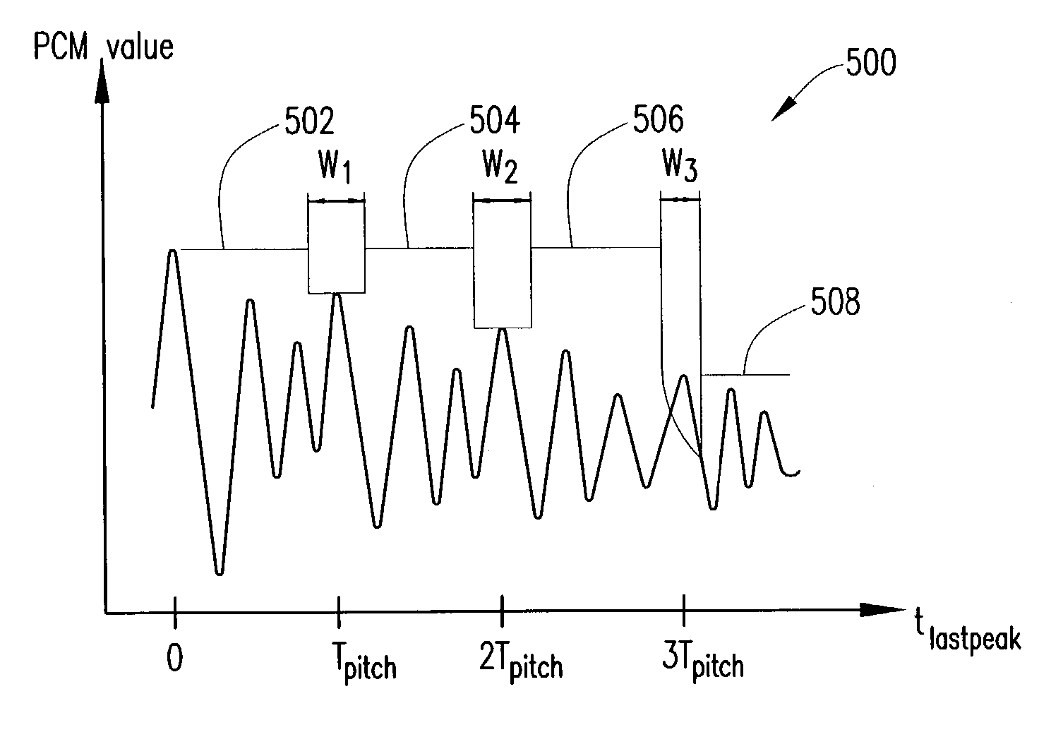
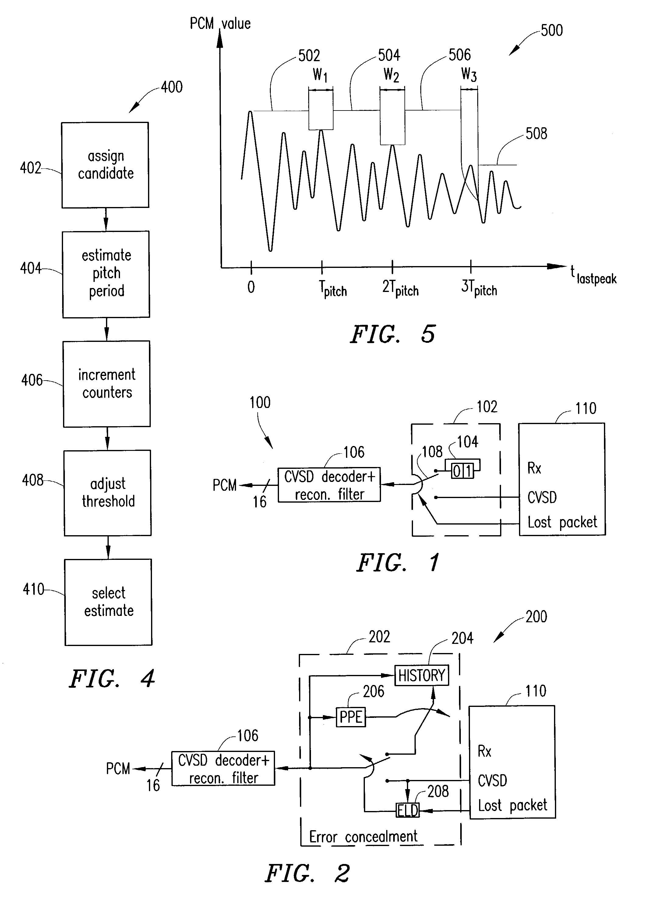
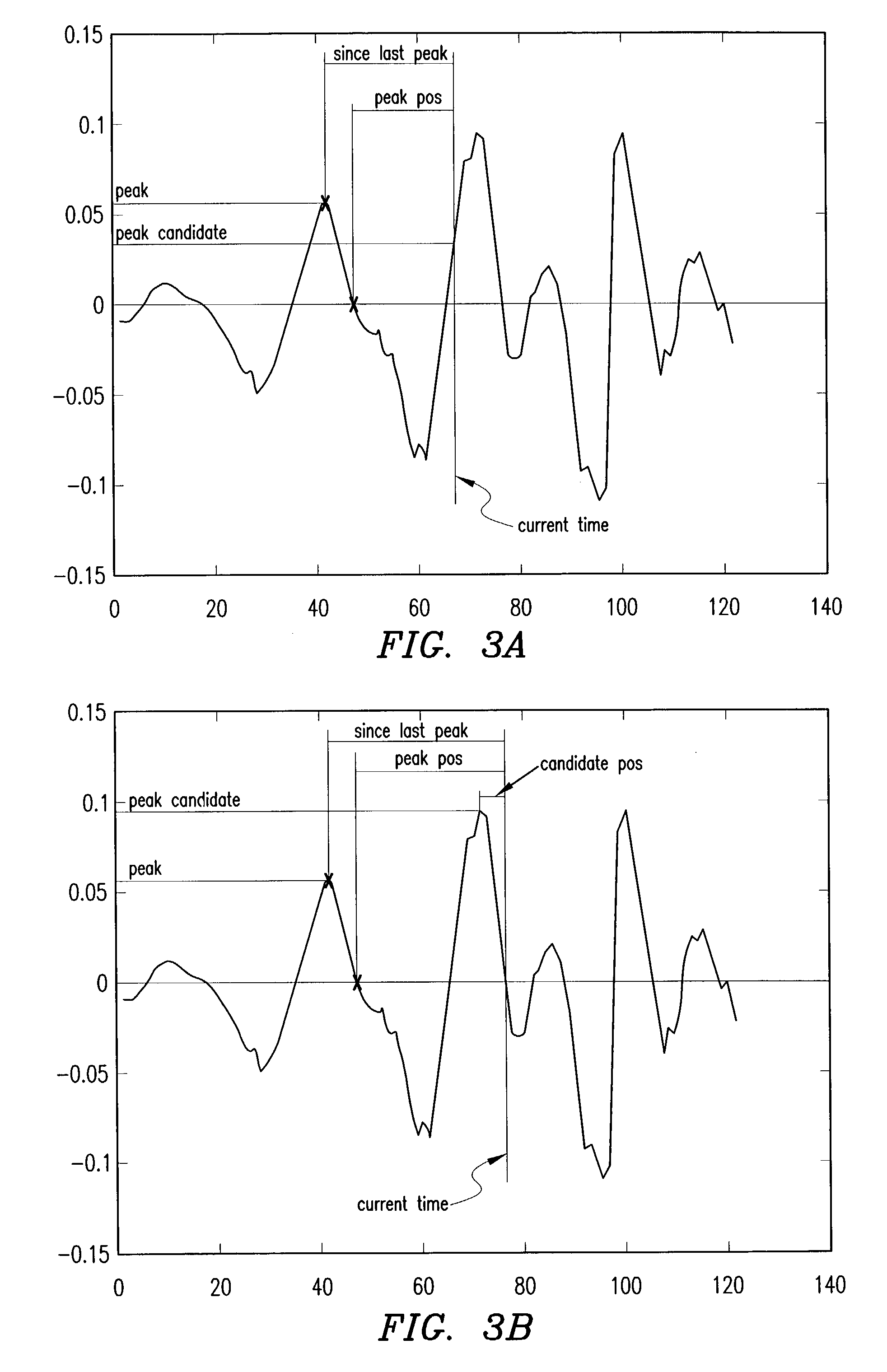
[0025] Embodiments of the present invention use time-domain properties of the speech signal to estimate the pitch period of the speech signal. In accordance with principles of the present invention, a time period between two subsequent zero crossings (that possess certain properties) of PCM samples of the speech signal is determined. Using zero crossings of the speech signal decreases noise impact. The noise is more apparent in the time domain when the derivative of the signal is near zero. However, a skilled person will realize that the algorithm can easily be altered to determine a tim...


PUM


Abstract

A pitch period of a signal is estimated by identifying a peak candidate of the signal as a peak and estimating the pitch period of the signal based on a time difference between the identified peak and a previous peak of the signal. An error-concealment apparatus includes a history block for storing signal data input to a decoder, an error likelihood detector, and a pitch period estimator. The error likelihood detector directs an input of the decoder to data of the signal data in the history block offset an estimated signal pitch period back in time responsive to a determination that data from a receiver has been lost or corrupted. The pitch period estimator estimates the pitch period of the signal via identification of peaks of the signal data.

Description

[0001] This patent application claims priority from and incorporates by reference the entire disclosure of U.S. Provisional Patent Application No. 60 / 374,039, which was filed on Apr. 19, 2002.[0002] 1. Technical Field of the Invention[0003] The present invention relates in general to pitch period estimation (PPE) and more particularly, to pitch period estimation for use in pitch period error concealment (PPEC) systems. The PPEC systems can be used in voice processing systems. For example, the PPEC systems can be used to eliminate voice impact of 2.4 GHz band interference in systems that utilize BLUETOOTH.[0004] 2. Description of Related Art[0005] In data connections, transmission of data is likely to be impaired by interference. In voice links in ad hoc wireless networks such as BLUETOOTH, interference is likely from microwave ovens, other BLUETOOTH links, or wireless transmission systems that operate in the frequency band of 2400-2500 MHz. An 802.11b wireless local area network (WL...

Claims


Application Information

Patent Timeline
IPC IPC(8): G10L19/00G10L25/90
CPCG10L19/005G10L2025/906G10L25/90G10L21/013
Inventor SVENSSON, HENRIKHANSSON, MATTIASABERG, JANMEKURIA, FISSEHA
Owner TELEFON AB LM ERICSSON (PUBL)
Learn More